


18 UDC 3300 Controller Product Manual 4/00
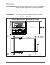
2.5 Wiring Diagrams
Composite wiring
diagram
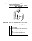
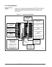
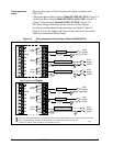
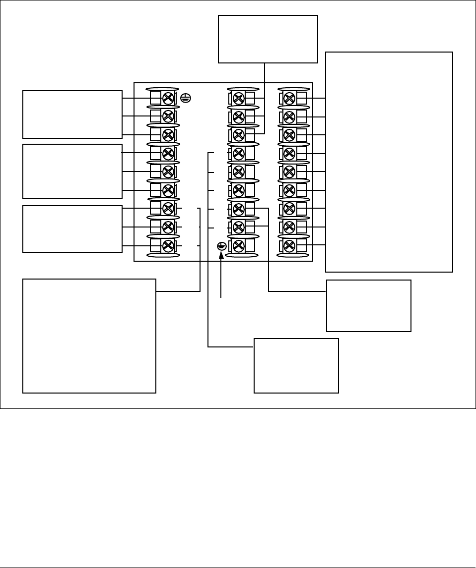
Figure 2-4 is a composite wiring diagram of the UDC 3300 controller. It
identifies the terminal designations and their functions. Refer to the
individual diagrams listed to wire the controller according to your
requirements.
Figure 2-4 Composite Wiring Diagram
1
2
3
4
5
6
7
8
9
L1
L2/N
22
23
24
Communications
Terminals
See Figures
2-17, 2-18
Auxiliary Output
Terminals
See Figure 2-15
Outputs and Alarms
Terminals
• Time Proportional Output
See Figures 2-8, 2-9, 2-10,
2-11
• Current Output/Universal
Output
See Figures 2-12, 2-13
• Position Proportional
Output
See Figure 2-14
For Control and Alarm Relay
Contact information, See
Tables 2-7 and 2-8.
Digital Inputs
Terminals
See Figure 2-16
AC Line Voltage
Terminals
See Figure 2-5
Input #2 Terminals
See Figure 2-6
Two HLAI Terminals
See Figure 2-7
Input #1
Terminals
See Figure 2-6
10
11
12
13
14
15
16
17
24158
Transmitter Power for
4-20 mA 2-wire
Transmitters
• Using Alarm 2 Output
See Figure 2-19
• Using Auxiliary Output
See Figure 2-20
I/O shield ground
(Do not use for
Communications shield)
25
26
27