


114 UDC 3300 Process Controller Product Manual 4/00
Lower Display
Prompt
Upper Display
Range of Setting
or Selection
Parameter
Definition
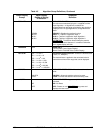
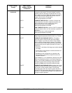
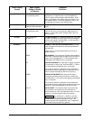
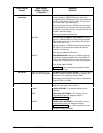
IN1 LO
–999. To 9999. Floating
(in engineering units)
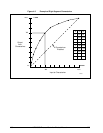
INPUT 1 LOW RANGE VALUE in engineering units is
displayed for all inputs but can only be configured for
linear or square root transmitter characterization. Scale
the #1 input signal to the display value you want for 0 %.
See example above. The control setpoint for Input 1 will
be limited by the range of units selected here.
RATIO 1
–20.00 to 20.00
Floats to 3 decimal places
RATIO ON INPUT 1—Select the Ratio value you want on
Input 1.
BIAS IN1
–999. to 9999.
(in engineering units)
BIAS ON INPUT 1 — Bias is used to compensate the
input for drift of an input value due to deterioration of a
sensor, or some other cause. Select the bias value you
want on Input 1.
FILTER 1
0 to 120 seconds
No filter = 0
FILTER FOR INPUT 1—A software digital filter is provided
for Input 1 to smooth the input signal. You can configure
the first order lag time constant from 1 to 120 seconds. If
you do not want filtering, enter 0.
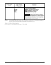
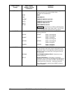
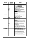
BURNOUT
NONE
UP
DOWN
NO_FS
BURNOUT PROTECTION (SENSOR BREAK) provides
most input types with upscale or downscale protection if
the input fails.
1-5V, 0-10V, or 4-20 mA inputs require no burnout or
NONE selection.
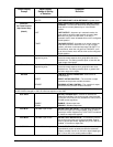
NO BURNOUT—Pre-configured Failsafe output applied if
failed input is detected (does not apply for an input out of
range). Error message INPUT 1 FAIL is flashed on the
lower display intermittently every 10 seconds.
UPSCALE BURNOUT will make the PV signal increase to
full scale when a sensor fails, and flash INPUT 1 FAIL on
the lower display intermittently every 10 seconds.
The controller remains in Automatic control mode and
adjusts the controller output signal in response to the full
scale PV signal developed by the Burnout circuitry.
DOWNSCALE BURNOUT will make the PV signal
decrease to the lower range value when a sensor fails,
and flash INPUT 1 FAIL on the lower display intermittently
every 10 seconds.
The controller remains in Automatic control mode and
adjusts the controller output signal in response to the zero
percent PV signal developed by the Burnout circuitry.
NO FAILSAFE—This selection does not provide input
failure detection and should only be used when an
absolute accuracy is the most important criteria. (For this
selection, no burnout signal is sent to the sensor.)
ATTENTION
For no Burnout, i.e. NONE, to function
properly on a 4-20 mA input, there must be a dropping
resistor directly across the input terminals (i.e., not
remote), then the unit can detect the “zero” voltage that
occurs when the 4-20 mA line is opened.