


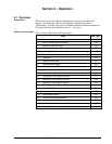
4/00 UDC 3300 Controller Product Manual 151
5.4 Monitoring Your Controller
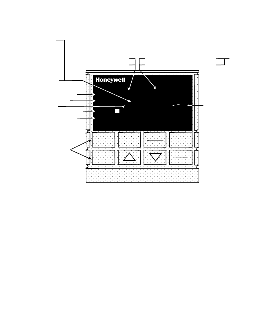
Operator interface
The indicators and displays on the operator interface let you see what is
happening to your process and how the controller is responding.
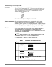
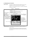
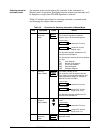
Figure 5-1 is a view of the operator interface. A description of the displays
and indicators is included.
Figure 5-1 Operator Interface
ALM
RSP
OUT
%
1 2 3
1 2
1 2
F C
MAN
FUNCTION
LOOP 1/2
SET UP
LOWER
DISPLAY
MANUAL
AUTO
SETPOINT
SELECT
RUN
HOLD
DI
3300
SP 3300
Indicator definition when lit
ALM - Alarm conditions exist
DI - Digital input active
OUT - Control relay 1 or 2 on
Upper Display - six characters
• Normal Operation - four digits dedicated to display the process variable
• Configuration Mode - displays parameter value or selection
Lower Display - eight characters
• Normal Operation - displays operating parameters and values
• Configuration Mode - displays function groups and parameters
MAN - controller in manual mode
A - controller in automatic mode
F - °Fahrenheit being used
C - °Centigrade being used
Indicator definition when lit
Deviation Bargraph
• Center bar indicates PV is
within ±1% of setpoint.
• Next bar will light if PV is
between ±1% but less than
±2% in deviation.
• If PV is equal to or greater than
±10% deviation, the center bar
plus all ten deviation bars will
light.
MAN and A off —
communications
option active
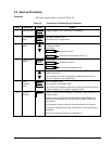
Keys - See Table 1-1
T - Accutune in progress
t - PV tune in progress
L" - Loop 2 display
I - Cascade control
C - Computer setpoint active
O - Output override active
R - Run SP ramp/program
H - Hold SP ramp/program
RSP - Remote SP or SP2 active
24157
R
3 - LSP 3 active
Decimal point position
In each display, when no decimal place is configured, the right-most
character is blank.
When a single decimal position has been configured and values greater
than 1000 are displayed, the right-most character is blank but the decimal
point will be lit.