


174 UDC 3300 Controller Product Manual 4/00
Internal cascade
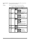
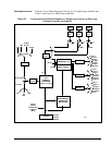
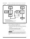
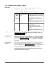
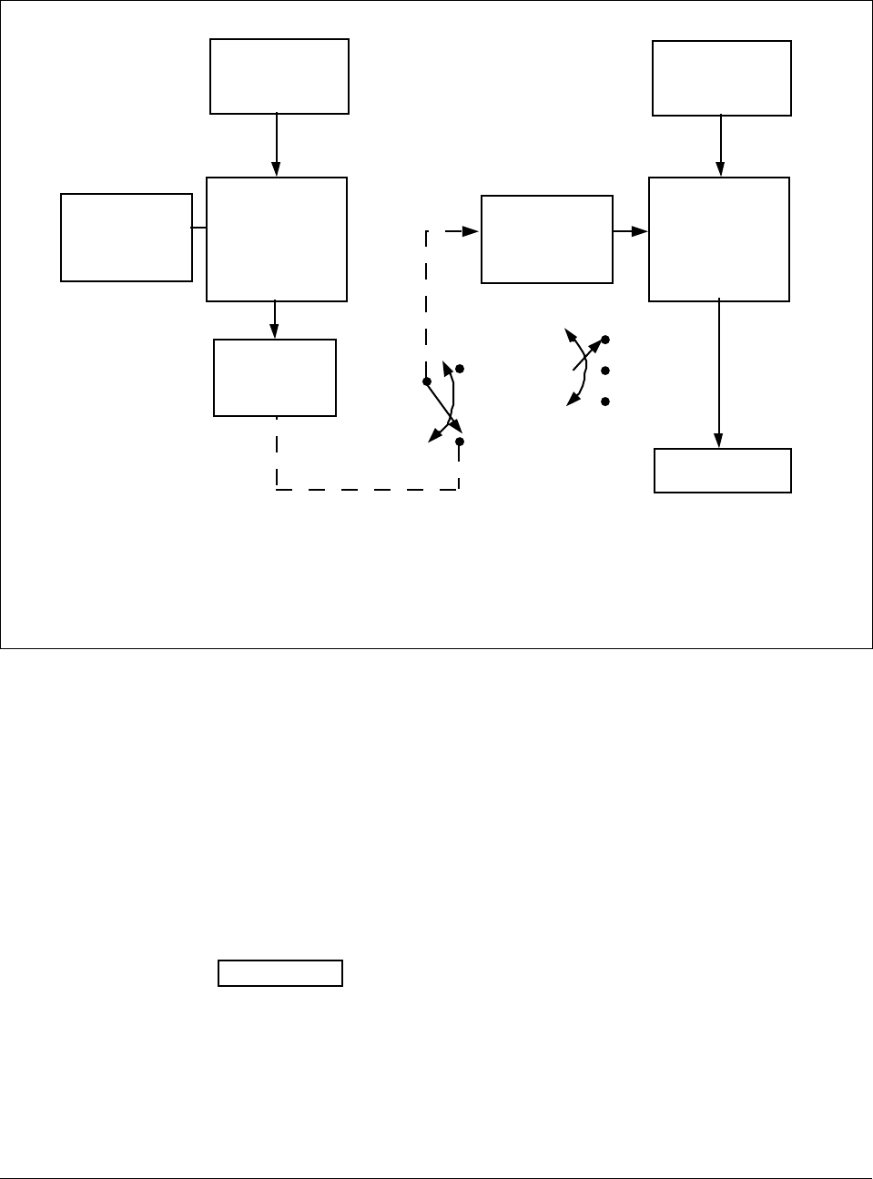
Figure 5-3 is a block diagram of internal Cascade for a 2-loop controller.
Figure 5-3 Functional Overview Block Diagram of Internal Cascade of a 2-loop Controller
PID
CONTROL
ALGORITHM
Loop 2
OUTPUT
To Final
Control
Element
PV SOURCE
See
Loop 2
Block Diagram
PRIMARY LOOP
PV SOURCE
See
Loop 1
Block Diagram
SECONDARY LOOP
PID
CONTROL
ALGORITHM
Loop 1
SETPOINT
SOURCE
Loop #1
INTERNAL
OUTPUT
SIGNAL
SETPOINT
SOURCE
See
Loop #2
Block Diagram
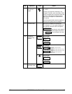
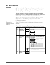
INTERNAL CASCADE RULES
• Loop #2 must be the primary loop.
• Loop #1 must be the secondary (internal or slave) loop
because all output forms exist on Loop 1.
• Loop #1 Remote Setpoint is fixed as loop #2 output.
24182
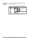
Remote Setpoint
Local Setpoint
SP
2SP
3SP
Override rules
The UDC 3300 allows you to select high or low output override. Refer to
Section 3 - Configuration to select High or Low.
The following rules apply for high/low override:
• Only one physical output is required when override is enabled. It is the
output from Loop 1 because Loop 2’s internal output is routed through
the selector.
• Loop 2 output can also be available at all times if desired.
• In Manual mode, the Output may be overridden.
• Does not apply for Three Position Step Control.
• OTI on bottom display shows value of the internal Loop 1 output
before any override.
ATTENTION
The output of the unselected loop tracks the selected loop
to within 5 % when in Auto mode to eliminate windup. This tracking is
done in the direction opposite to the Override Select configuration; i.e., for
High Select, the unselected output tracks within 5 % of lower, and vice
versa.