


4/00 UDC 3300 Controller Product Manual 3
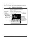
1.2 Operator Interface
Displays and indicators
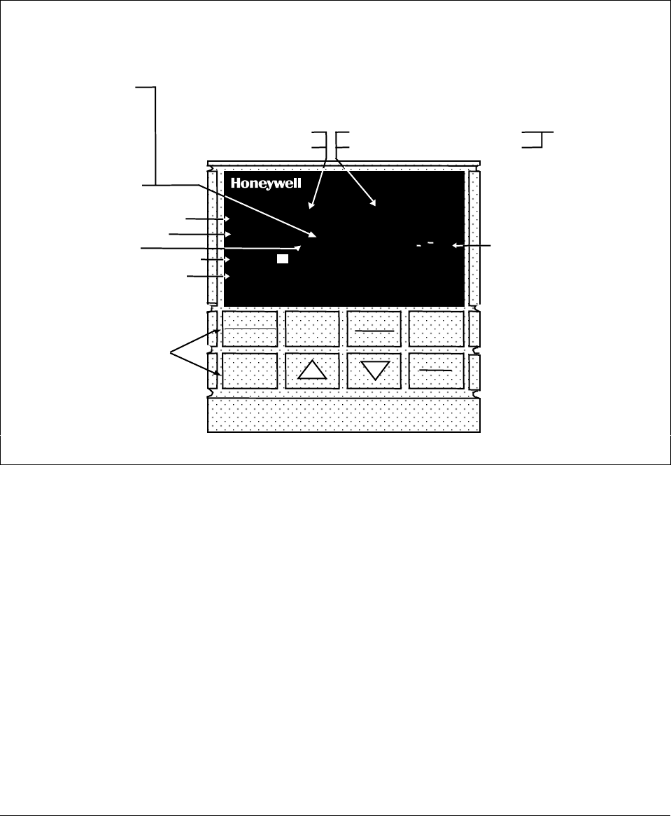
Figure 1-1 shows the operator interface and defines the displays and
indicators. The function of the keys is shown in Table 1-1.
Figure 1-1 Operator Interface Displays and Indicators
ALM
RSP
OUT
%
1 2 3
1 2
1 2
F C
MAN
FUNCTION
LOOP 1/2
SET UP
LOWER
DISPLAY
MANUAL
AUTO
SETPOINT
SELECT
RUN
HOLD
DI
3300
SP 3300
Indicator definition when lit
ALM - Alarm conditions exist
DI - Digital input active
OUT - Control relay 1 or 2 on
Upper Display - six characters
• Normal Operation - four digits dedicated to display the process variable
• Configuration Mode - displays parameter value or selection
Lower Display - eight characters
• Normal Operation - displays operating parameters and values
• Configuration Mode - displays function groups and parameters
MAN - controller in manual mode
A - controller in automatic mode
F - °Fahrenheit being used
C - °Centigrade being used
Indicator definition when lit
Deviation Bargraph
• Center bar indicates PV is
within ±1% of setpoint.
• Next bar will light if PV is
between ±1% but less than
±2% in deviation.
• If PV is equal to or greater than
±10% deviation, the center bar
plus all ten deviation bars will
light.
MAN and A off —
communications
option active
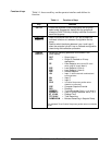
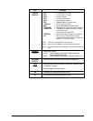
Keys - See Table 1-1
T - Accutune in progress
t - PV tune in progress
L" - Loop 2 display
I - Cascade control
C - Computer setpoint active
O - Output override active
R - Run SP ramp/program
H - Hold SP ramp/program
RSP - Remote SP or SP2 active
24157
R
3 - LSP 3 active