


4/00 UDC 3300 Process Controller Product Manual 105
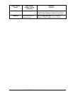
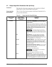
Lower Display
Prompt
Upper Display
Range of Setting
or Selection
Parameter
Definition
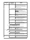
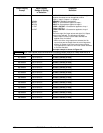
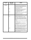
8SEG CH2
DISABL
INPUT1
INPUT2
L1 OUT
L2 OUT
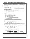
8 SEGMENT CHARACTERIZER #2—A second eight
segment characterizer can be applied to either
Input 1, Input 2, Output 1, or Output 2.
DISABLE—Disables characterizer.
INPUT 1—Characterizer applied to Input 1.
INPUT 2—Characterizer applied to Input 2.
LOOP 1 OUTPUT—Characterizer applied to Loop 1
Output. (NOTE 1)
LOOP 2 OUTPUT—Characterizer applied to Loop 2
Output.
There are eight (Xn) Input values and eight (Yn) Output
values to be selected. The following rules apply:
• When Input 2 is used, Input 2 Ratio and Bias are
applied to the Xn Values.
• When one of the Loop outputs are selected, the Xn
Input values are the Output from the control algorithm,
and the Yn Output is the final control element action.
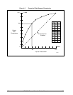
This application is useful for non-linear control elements
or Process Variable.
A simple example is shown in Figure 4-2.
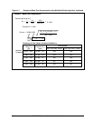
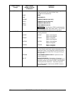
ATTENTION The X values below should be entered as increasing values (from 0% to 100%) from N=0 to 8.
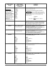
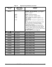
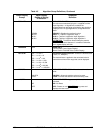
X0 VALU2
0.00 to 99.99 %
X0 INPUT VALUE (X AXIS)
X1 VALU2
0.00 to 99.99 %
X1 INPUT VALUE (X AXIS)
X2 VALU2
0.00 to 99.99 %
X2 INPUT VALUE (X AXIS)
X3 VALU2
0.00 to 99.99 %
X3 INPUT VALUE (X AXIS)
X4 VALU2
0.00 to 99.99 %
X4 INPUT VALUE (X AXIS)
X5 VALU2
0.00 to 99.99 %
X5 INPUT VALUE (X AXIS)
X6 VALU2
0.00 to 99.99 %
X6 INPUT VALUE (X AXIS)
X7 VALU2
0.00 to 99.99 %
X7 INPUT VALUE (X AXIS)
X8 VALU2
0.00 to 99.99 %
X8 INPUT VALUE (X AXIS)
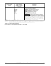
Y0 VALU2
0.00 to 99.99 %
Y0 INPUT VALUE (Y AXIS)
Y1 VALU2
0.00 to 99.99 %
Y1 INPUT VALUE (Y AXIS)
Y2 VALU2
0.00 to 99.99 %
Y2 INPUT VALUE (Y AXIS)
Y3 VALU2
0.00 to 99.99 %
Y3 INPUT VALUE (Y AXIS)
Y4 VALU2
0.00 to 99.99 %
Y4 INPUT VALUE (Y AXIS)
Y5 VALU2
0.00 to 99.99 %
Y5 INPUT VALUE (Y AXIS)
Y6 VALU2
0.00 to 99.99 %
Y6 INPUT VALUE (Y AXIS)
Y7 VALU2
0.00 to 99.99 %
Y7 INPUT VALUE (Y AXIS)
Y8 VALU2
0.00 to 99.99 %
Y8 INPUT VALUE (Y AXIS)