


4/00 UDC 3300 Process Controller Product Manual 229
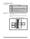
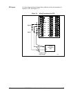
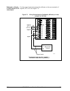
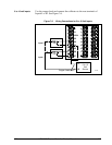
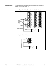
7.5 Input #1, #2, or #3 Calibration Procedure
Introduction
Apply power and allow the controller to warm up for 15 minutes before
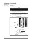
you calibrate. Read “Set Up Wiring” before beginning the procedure.
Make sure you have LOCKOUT set to NONE. See Section 3 –
Configuration.
CAUTION
For linear inputs, avoid step changes in inputs. Vary smoothly
from initial value to final 100 % value.
Procedure
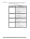
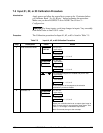
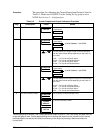
The Calibration procedure for Input #1, #2, or #3 is listed in Table 7-5.
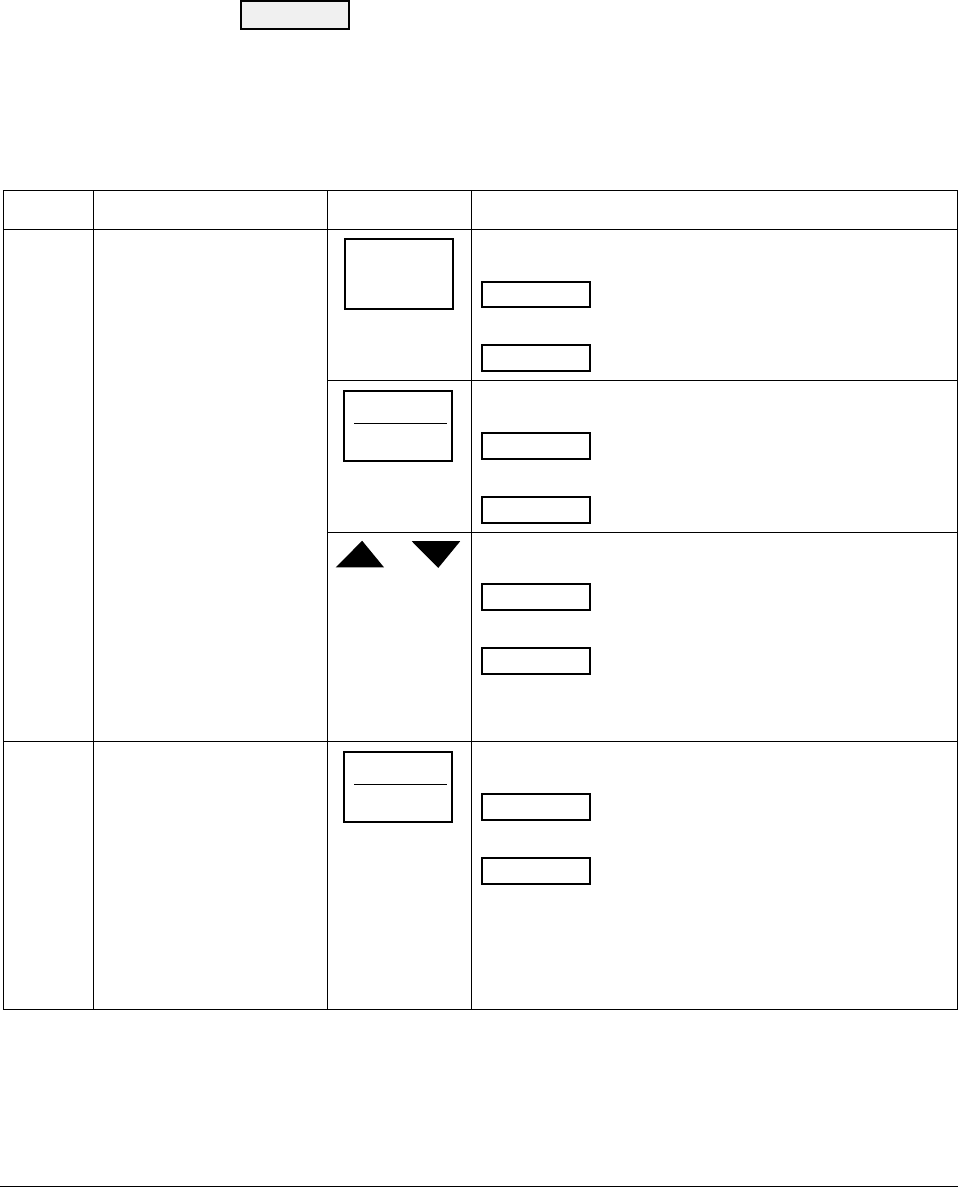
Table 7-5 Input #1, #2, or #3 Calibration Procedure
Step Description Press Action
1
Enter Calibration Mode
SET UP
until you see
INPUT n
Lower Display
CALIB
Upper Display
n = 1, 2, or 3
FUNCTION
LOOP 1/2
You will see:
CAL IN n
Lower Display
DISABL
Upper Display
n = 1, 2, or 3
or
The calibration sequence is enabled and you will see:
CAL IN n
Lower Display
BEGIN
Upper Display
n = 1, 2, or 3
At the completion of the sequence, the selection
automatically reverts to disable.
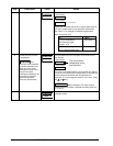
2
Calibrate 0 %
FUNCTION
LOOP 1/2
You will see:
INn ZERO
Lower Display
APPLY
Upper Display
n = 1, 2, or 3
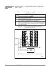
Adjust your calibration device to an output signal equal to
the 0 % range value for your particular input sensor. See
Table 7-1 for Voltage or Resistance equivalents.
Wait 15 seconds, then go to the next step.