


224 UDC 3300 Process Controller Product Manual 4/00
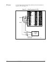
Thermocouple inputs
using a precision
resistor
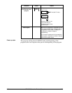
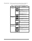
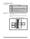
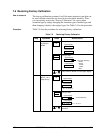
Referring to Figure 7-3, wire the controller according to the procedure
given in Table 7-4.
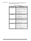
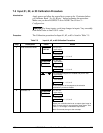
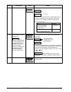
Table 7-4 Set Up Wiring Procedure for Thermocouple Inputs
Using a Precision Resistor
Step Action
1
Connect the copper leads to the calibrator.
2
Disconnect the cold junction resistor.
3
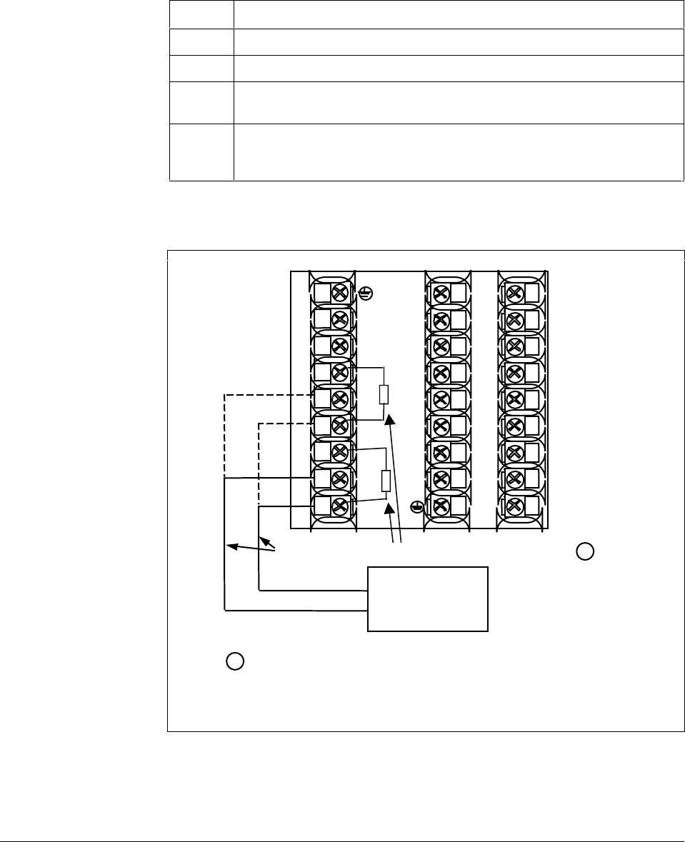
Install a 500-ohm precision resistor across Input 1 terminals 25 (R) and
27 (–) or Input 2 terminals 22 (R) and 24 (–). See Figure 7-3.
4
Subtract the millivolt value for 77 °F (25 °C) from the zero and span value for
your range (see Table 7-1 for zero and span values) and use the adjusted
value when calibrating.
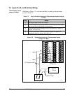
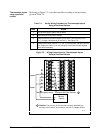
Figure 7-3 Wiring Connections for Thermocouple Inputs
Using a Precision Resistor
1
2
3
4
5
6
7
8
9
10
11
12
13
14
15
16
17
L1
L2/N
22
23
24
25
26
27
+
–
Precision 500 Ohm Resistor
Copper Leads
Millivolt
Source
+
–
R
1
1
Caution:
The accuracy of the controller is directly affected by the
accuracy of this resistor. At a minimum, use a 0.1%, 25ppm resistor.
24175
+
–
R
Input 2
Input 1