


4/00 UDC 3300 Controller Product Manual 263
How to replace the
display/keyboard
assembly
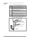
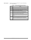
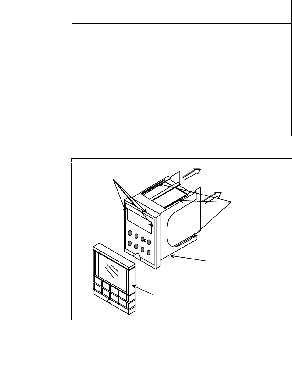
Refer to Figure 9-2 and follow the procedure listed in Table 9-17.
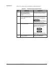
Table 9-17 Display/Keyboard Assembly Replacement Procedure
Step Action
1
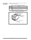
Remove the chassis from the case as shown in Figure 9-1.
2
Peel the rubber bezel and display window off the chassis assembly.
3
Separate the chassis frame at the four release points shown in Figure 9-2
and wiggle each printed wiring board out of its socket on the
display/keyboard assembly. Pull out slightly.
4
Insert a small flat-bladed screwdriver into each of the display/keyboard
release points (Figure 9-2) and pry out the board.
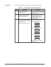
5
Install the new board, bottom end in first, and push in the top until it clicks
into place.
6
Reinstall the printed wiring boards into the rear of the display board
making sure that the boards click into their release points.
7
Replace the bezel and window assembly.
8
Reinstall chassis into case. Press in hard, then tighten the screw.
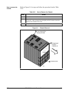
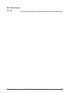
Figure 9-2 Display/Keyboard Replacement
Display keyboard
release points
Pull printed
wiring boards
out slightly
Printed wiring
boards
release points
Display/keyboard
Chassis assembly
Rubber bezel
and window
22638