


4/00 UDC 3300 Controller Product Manual 203
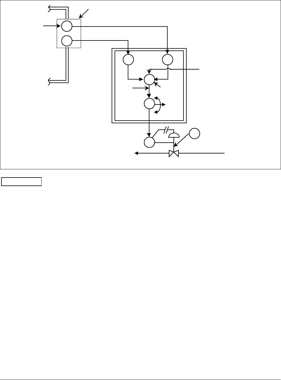
Diagram
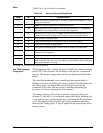
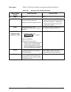
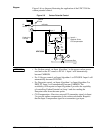
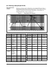
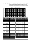
Figure 5-6 is a diagram illustrating the application of the UDC 3300 for
carbon potential control.
Figure 5-6 Carbon Potential Control
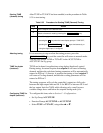
T/C
f(x) f(x)
PID
E/P
CV
Carbon
Probe
O
2
Sensor
Carburizing
Furnace
%
Carbon
PV
%
Carbon
Calc.
Output
Enrichment Gas
• SP
• 2SP
• 3SP or
RSP
Input 2 Input 1
UDC 3300
24185
millivolts
CP
Input 3—
Optional Online
CO Compensation
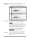
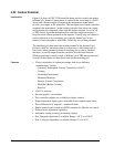
ATTENTION
• For Carbon control, set Input Algorithm 1 to the proper carbon sensor
used and set the PV source to IN AL 1. Input 1 will automatically
become CARBON.
• For % Oxygen control, set Input Algorithm 1 to OXYGEN. Input 1 will
automatically become OXYGEN.
• For Dewpoint control, set Input Algorithm 1 or Input Algorithm 2 to
DEW PT. Input 1 will automatically become CARBON. The
availability of Dewpoint on Input Algorithm 2 provides the capability
of controlling Carbon Potential on Loop 1 and also reading the
Dewpoint value from the same probe.
• CO Compensation—Receives external CO transmitter signal via Input
3 to provide online compensation fo the carbon calculation. Requires
that the Input 2 temperature signal be a transmitter type input.