


4/00 UDC 3300 Controller Product Manual 19
Line voltage wiring
This equipment is suitable for connection to 90-264 Vac or 24 Vac/dc,
50/60 Hz, power supply mains. It is the user’s responsibility to provide a
switch and non-time delay (North America), quick-acting, high breaking
capacity, Type F, (Europe) 1/2 A, 250 V fuse(s) or circuit-breaker for 90-
264 V; or 1 A, 125 V fuse or circuit breaker for 24 Vac/dc operation, as
part of the installation. The switch or circuit-breaker should be located
close to the controller, within easy reach of the operator. The switch or
circuit-breaker should be marked as the disconnecting device for the
controller (4 mm
2
).
CAUTION
Applying 90-264 Vac to a controller rated for 24 Vac/dc
will severely damage the controller and is a fire and smoke hazard.
When applying power to multiple instruments, make sure that sufficient
current is supplied. Otherwise, the instruments may not start up normally
due to the voltage drop caused by the in-rush current.
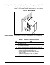
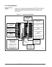
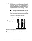
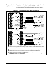
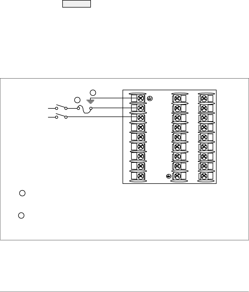
Figure 2-5 shows the wiring connections for line voltage.
Figure 2-5 Line Voltage Wiring
1
2
3
4
5
6
7
8
9
10
11
12
13
14
15
16
17
L1
L2/N
22
23
24
25
26
27
Ground
Hot
Neutral
AC/DC
Line
Voltage
PROTECTIVE BONDING (grounding) of this controller and the enclosure in which it is installed, shall be
in accordance with National and local electrical codes. To minimize electrical noise and transients that
may adversly affect the system, supplementary bonding of the controller enclosure to a local ground,
using a No. 12 (4 mm
1
2
1
2
22607
2
) copper conductor, is recommended.
Provide a switch and non-time delay (North America), quick-acting, high breaking capacity, Type F, (Europe)
1/2 A, 250 V fuse(s) or circuit-breaker for 90-264 V; or 1 A, 125 V fuse or circuit breaker for 24 Vac/dc
operation, as part of the installation.