


32 UDC 3300 Controller Product Manual 4/00
Transmitter power for
4-20 mA 2-wire
transmitter—open
collector alarm 2 output
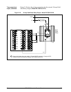
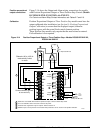
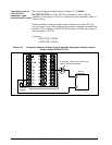
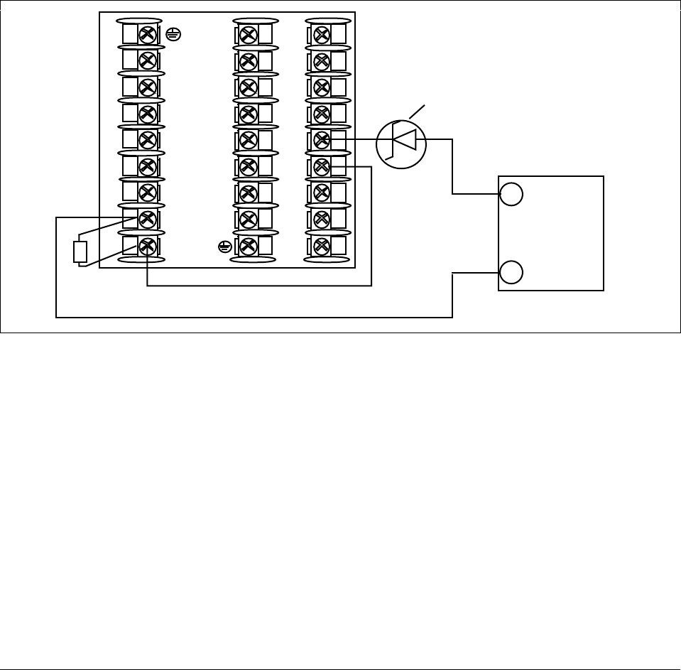
The wiring diagram example shown in Figure 2-19 (Model
DC330X-XT-XXX) provides 30 Vdc at terminals 5 and 6 with the
capability of driving up to 22 mA, as required by the transmitter which is
wired in series.
If the transmitter terminal voltage must be limited to less than 30 volts,
you can insert a zener diode between the positive transmitter terminal and
terminal 5. For example, an IN4733A zener diode will limit the voltage at
the transmitter to 25 Vdc.
Configure:
A2S1TYPE = NONE
A2S2TYPE = NONE
Figure 2-19 Transmitter Power for 4-20 mA 2-wire Transmitter Using Open Collector Alarm 2
Output—Model DC330X-XT-XXX
24171
1
2
3
4
5
6
7
8
9
L1
L2/N
22
23
24
10
11
12
13
14
15
16
17
25
26
27
+
–
2-wire
Transmitter
250 ohm
resistor
+
–
+
–
If necessary, install zener diode here to
reduce voltage at transmitter.