


26 UDC 3300 Controller Product Manual 4/00
Current output/
universal output
connections
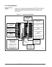
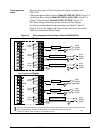
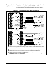
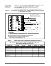
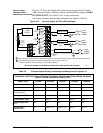
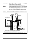
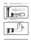
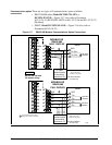
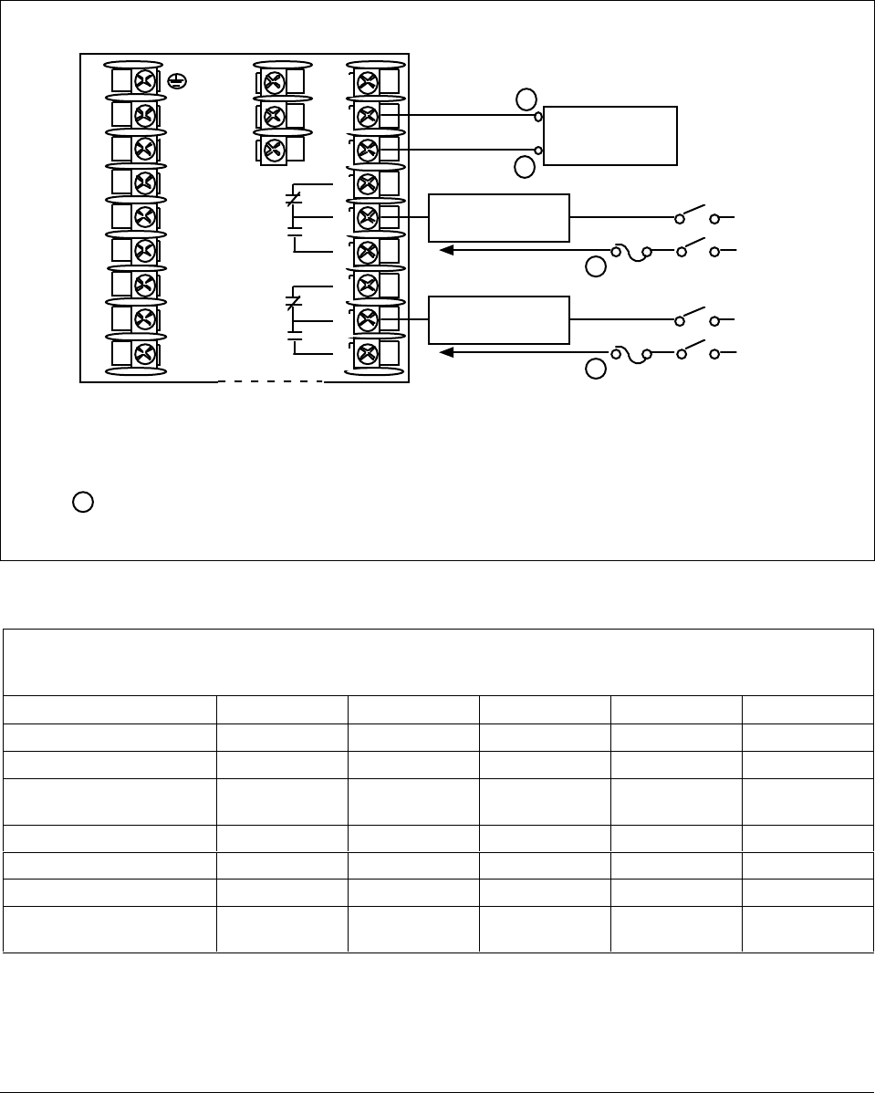
Figure 2-12 shows the Output and Alarm wiring connections for models
with Current Output (Model DC330X-KE-XXX and Model
DC330X-C0-XXX). See Table 2-5 for wiring restrictions.
For Control and Alarm Relay Contact information, see Tables 2-7 and 2-8.
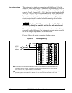
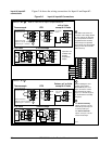
Figure 2-12 Current Output—Current /Time Duplex, Time/Current Duplex, Position Proportional,
or Three Position Step Control
+
ATTENTION:
All current outputs are isolated from each other, case ground, and all inputs.
L1
L2/N
22
23
24
25
26
27
10
11
12
Controller Load
0–1000 Ohms
–
Current Output
4–20 mA
N.C.
N.O.
N.O.
N.C.
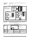
For Duplex Current Output use Auxiliary Output for Output 2 (cool) (see Figure 2-14).
To terminal
7 or 9
Output#1
or
Alarm#2
Relay
To terminal
4 or 6
Load
Supply
Power
Output or Alarm
Relay 2 Load
Load
Supply
Power
Output or Alarm
Relay 3 Load
24167
Output#2
or
Alarm#1
Relay
See Table 2-7 for relay
terminal connections for
Output Algorithm selected.
1
2
3
4
5
6
7
8
9
Electromechanical relays are rated at 5 Amps @120 Vac or 2.5 Amps at 240 Vac.
Customer should size fuses accordingly. Use Fast Blo fuses only.
Relays are NOT available on DC330X-C0-XXX.
1
1
1
Table 2-5 Universal Output Wiring Functionality and Restrictions for Figure 2-12
Controller with Two Current Outputs and Two Relay Outputs
SINGLE LOOP OR CASCADE CONTROL OUTPUT
Output Type Current Auxiliary Relay #1 Relay #2 Relay #3
Time Simplex
Not used Not used N/A Output 1 Alarm 1
Current
Output 1 Not used N/A Alarm 2 Alarm 1
Position (not available on
Cascade Control)
Not used Not used N/A Output 1 Output 2
Time Duplex or TPSC
Not used Not used N/A Output 1 Output 2
Current Duplex 100%
Output 1 Not used N/A Alarm 2 Alarm 1
Current Duplex 50%
Output 1 Output 2 N/A Alarm 2 Alarm 1
Current/Time or
Time/Current
Output 1 or 2 Not used N/A Output 1 or 2 Alarm 1