


8-4 Troubleshooting MN792
Manage Trips from the Keypad
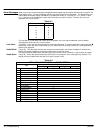
Trip Messages Most of the alarms have a delay timer so that the control only trips if the condition persists for the whole of the
delay period. If the control trips, the display immediately shows a message indicating the reason for the trip.
These messages are shown in Table 8-4.
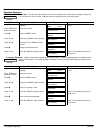
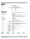
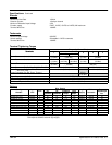
Table 8-4
Trip Message and Description Possible Cause
Overspeed
Motor overspeed – the speed feedback signal
has exceeded 125% of rated speed.
Badly adjusted speed loop (alarm only operates with encoder or armature volts
feedback selected)
Alarm time delay : 0.1 seconds
Missing Pulse
A missing pulse from the 6–pulse armature
current waveform. Trips when the motor loading
exceeds 1.5 times the Discontinuous parameter
value.
Firing plug failure
Connection failure
Alarm time delay : 60 seconds
Field Over I
The motor field current has exceeded 120% of
the calibrated value
Regulator failure
Badly tuned control loop (alarm only operates with field current control mode
selected)
Alarm time delay : 15 seconds
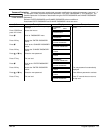
Heatsink Trip
The control heatsink temperature is too high
The ambient air temperature is too high
Poor ventilation or spacing between controls
Fan failure, check fuse on power board, wrong rotation (models above 70A bridge
rating)
Blocked ventilation slots Clogged air filters
Excessive armature current – nominal armature current on motor nameplate
should be checked against the current calibration for the control. The stack must
be allowed to cool in order to re–start the control.
Alarm time delay : 0.75 seconds
Thermistor
The motor temperature is too high
Inadequate ventilation
Blower failure –check for direction, clogged air filters (models above 70A bridge
rating)
Excessive armature current – check nominal armature current on nameplate
against current calibration)
The motor must be allowed to cool in order to re–start the control.
Alarm time delay : 15 seconds
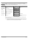
Over Volts (VA)
Motor armature voltage has exceeded 120% of
rated volts
Loose armature connection
Badly adjusted field voltage setting
Badly adjusted field current loop
Badly adjusted field–weakening bemf loop
Badly adjusted speed loop
Alarm time delay : 1.5 seconds
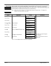
Speed Feedback
The difference between speed feedback and
armature voltage feedback is greater than the
SPDFBK ALM Level parameter value
If FLD Weak Enable parameter is enabled,
speed feedback is less than 10% when in the
field weakening region
Analog tachometer feedback polarity incorrect (terminals G3 and G4)
The ENCODER SIGN parameter’s polarity is incorrect
Tachometer failure
Tachometer coupling failure
Alarm time delay : 0.4 seconds
Encoder Failed
No speed feedback signal
The SPEED FBK SELECT parameter is set to ENCODER but an optional
Encoder board is not installed.
Check cable and connections on wire–ended encoder
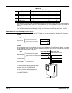
Field Fail
Field current is less than 6% of rated current
when in Current Control mode
Field current is less than 50mA when in Voltage
Control mode (with default current burden of
15K)
Open circuit motor field – check connection and measure field resistance
Faulty operation of field controller
Where an AC supply feeds the onboard field regulator, check connections FL1 &
FL2 for line–to–line voltage (rather than line–to–neutral) – L1 into FL1, L2 into
FL2. The 3–phase supply must be present for synchronization. For loads where
no field supply is required, e.g. a permanent magnet motor, set the FIELD
ENABLE parameter to disable to suspend this alarm.
Alarm time delay : 0.75 seconds