


Switch Setting & Start-Up 5-13MN792
Speed Loop Adjustment You will need to adjust the Speed Loop for your application although in most cases the factory
settings are acceptable. The optimum Speed Loop performance is achieved by adjusting the
PROP. Gain and INT. Time CONST. parameters.
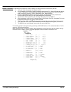
1. Produce a small step–change to the speed setpoint and observe the response on the tachometer
feedback or analog output set to speed feedback.
2. Adjust PROP. Gain and INT. Time CONST. parameters until you have rapid change of speed
feedback between the setpoint values with minimum overshoot.
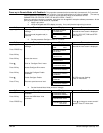
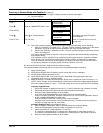
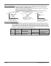
Incorrect Speed Response
Speed
Time
Underdamped response
causing overshoot or ringing
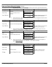
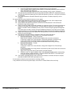
Incorrect Speed Response
Speed
Time
Overdamped response
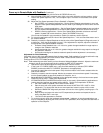
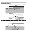
Correct Response
Speed
Time
4%
Critically damped response with no
more than 4% of max speed from 1st
overshoot to first undersoot.
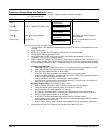
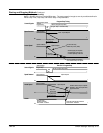
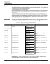
Starting and Stopping Methods
A Series 29 “non–regenerative” (2–quadrant) control coasts to a stop when the current demand reverses. A
Series 30 “regenerative” (4–quadrant) control can stop faster because it uses energy from the load, i.e. reverse
current is allowed to flow. The normal Stop and Program Stop are only relevant for a “regenerative” controller.
The parameters Stop Time and PROG Stop Time have associated timers which initiate a Coast Stop after the
timed period. The Coast Stop has direct control of the Run relay with no intervening electronics. All associated
parameters can be found in the Setup Parameters::Stop Rates menu.
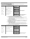
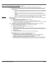
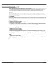
Terminal
Description Function Parameter Priority
B8 Program Stop Motor decelerates at
Program Stop rate
PROG STOP TIME Overrides Normal Stop
B9 Coast Stop Motor coasts to rest Overrides Program Stop
and Normal Stop
C3 Start/Run
(Normal Stop)
Motor decelerates at
Normal Stop rate
STOP TIME