


Section 5
Switch Setting and Start-Up
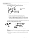
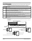
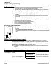
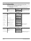
Power Board
SW2
SW1
HI
LO
HI
LO
IF CAL
IA CAL
Switch Setting & Start-Up 5-1MN792
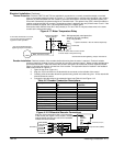
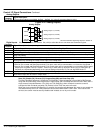
Pre–Operation Checks
When the installation is complete, several things should be verified before power is applied.
1. Be sure AC power is off at the main disconnect or circuit breakers.
2. Measure the main AC supply voltage (to the disconnect or breaker) and verify that it matches the
nameplate rating of the control.
3. If the catalog number on the nameplate ends with “CO1”, an external 115VAC logic control supply is
required (C02= 230VAC Logic). Verify Auxiliary power supply voltage is correct.
4. Verify the armature voltage and current ratings of the motor are correct.
5. Inspect all power connections (line and motor) for accuracy, workmanship tightness and compliance
to codes.
6. Verify that the control and motor are grounded to each other and that the control is connected to
earth ground.
7. Verify all signal wiring for accuracy and tightness.
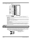
8. Be certain that all contactor, brake or relay coils have noise suppression. This should be an RC filter
for AC coils or a reverse biased diode for DC coils. MOV type transient suppression is not adequate.
9. Disconnect the load from the motor shaft if possible.
10. If possible, verify the motor shaft rotates freely.
11. Verify the cooling fan (blower) is free from obstruction.
12. Verify that the external run contacts are open.
13. Verify that external speed setpoints are all zero.
Size 4 and 5 Only – Power Board Calibration
IA CAL – Armature Current Calibration Switch (SW1)
This switch is always set to LO on Frame 4 & 5 drives of less than 500A, and HI for drives greater
than 500A.
F CAL – Field Current Calibration Switch (SW2)
This switch should always be set to HI for Frame 4 & 5 drives. The maximum field current calibration
is 30A.
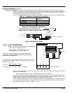
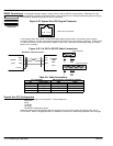
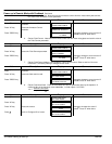
Power up in Local Mode with Armature Feedback
When pre–operation checks are complete, logic power can be applied to terminals L and N to setup the
software parameters (catalog number C01=115VAC, C02=230VAC). For other catalog numbers (100hp and
less), the logic power is provided internally so 3 phase power must be applied at this time.
(The start up mode is defined by Parameter [517] =True for keypad operation which is the same as “SETUP
PARAMETERS::OP STATION::START UP VALUES::LOCAL = TRUE”.)
Note: To separate the various menu level designation, a double colon is used (SETUP PARAMETERS::OP
STATION).
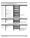
1. Apply logic power.
2. Verify that the keypad and LED’s display correctly. If not, verify that the logic wiring is correct.
Action Description Display Comments
Apply Logic Power
at terminals L and N
Keypad Display shows this opening
message.
INITIALIZING
LED’s are all ON.
BALDOR DC DRIVE
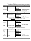
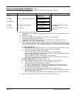
CALIBRATING
LED’s are flashing. After several
seconds the next screen is displayed.
If [517] is True, local mode will be
displayed (factory setting)
FORWARD
REF: 0.00%
The OK, SEQ, REF, FWD and STOP
LED’s are on.