


Section 1
Quick Start
Quick Start 1-1MN792
The basic steps for connection and setup are provided in this section. Detailed descriptions of each step and
parameter settings are provided later in this manual. Be sure to comply with all applicable codes when installing
this control. The Series 29 DC control is a one way control. That is, it is non–regen and cannot reverse
direction. It operates in the forward direction only. All references to reverse operation or regen operation apply
to the Series 30 DC Control only.
Minimum Connection Requirements Refer to Section 4 for cover removal procedure.
Power and Motor Connections
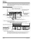
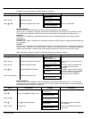
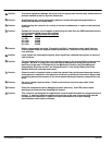
Figure 1-1 shows the minimum connections required at the power connector.
Figure 1-1 Power Connections
3 Phase
Power
Armature
Field
Thermistor
L1
L2
L3
GND
or jumper TH1 to TH2 if
motor thermistor is not connected.
To 1 Phase 115VAC Control Power
(except units with internal
control transformer,
100hp and less)
Motor Blower connections when using optional
Motor Starter on Size 1 & 2 controls.
For Size 1 & 2 controls, be sure the
logic power jumper is in the correct
position. Refer to Figure 4-9.
Reference and Jumpers for Keypad Operation
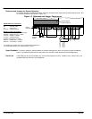
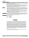
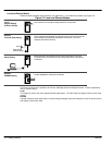
For keypad operation, the speed reference connections are not required. Speed is set at the keypad. Figure
1-2 shows the minimum connections required A, B and C signal connectors for Keypad operation.
Figure 1-2 Reference and Jumper Connections
Signal Connections
Minimum jumper connections:
A1 to A2 – 500 ohm jumper for 20mA input
A6 to B3 – Analog Input 5 = +10VDC
B8 to C9 – PROG Stop = +24VDC
B9 to C9 – Coast Stop = +24VDC
C4 to C9 – Enable = +24VDC
C1 to C2 – No External Trip
500 ohm
Jumper for
0-20mA
500
0V 1
AnIn 1 2
AnIn 2 3
AnIn 3 4
AnIn 4 5
AnIn 5 6
AnOut 1 7
AnOut 2 8
Arm I Fbk 9
0V 1
Not Used 2
+10V Ref 3
-10V Ref 4
DigOut 1 5
DigOut 2 6
DigOut 3 7
Prog Stop 8
Coast Stop 9
0V 1
Ext Trip 2
Start 3
DigIn E 4
DigIn R 5
DigIn 1 6
DigIn 2 7
DigIn 3 8
+24V 9
AB
C
If Optional Speed Feedback Board is used, refer
to Speed Feedback at the end of this section.
Parameter Settings (for Keypad Operation)
The factory settings should be sufficient to operate the control using the “Local” mode with the keypad. Only a
few changes to the motor data parameters must be made. Before any parameters can be changed, set
System::Configure I/O::Configure Enable to enable. All LEDs will blink during configuration.
Note: To separate the various menu level designation, a double colon is used (System::Configure I/O).