


Receiving & Installation 4-15MN792
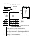
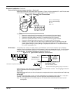
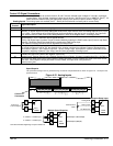
Control I/O Signal Connections
All connections made to terminal blocks A, B and C must be isolated signal voltages. If in doubt a connection,
contact Baldor. Only shielded, twisted pair cables should be use. Minimum wire size is 18AWG (0.75mm
2
). All
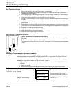
cables should be installed using the appropriate coupling in the knock out panel, shown in Figure 4-3.
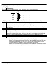
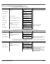
Analog Inputs Five analog inputs are available, AnIn1 – AnIn5 (AnIn4 and AnIn5 are factory set for current limits).
Connector
Terminal
Signal Description
A1 0V common reference point for all analog signals.
A2 Analog Input 1. 0–20 or 4–20mA analog input speed input. Used as a unipolar 0–20mA ramped speed command
channel. 4–20mA requires manually setting Min value to 25%, Max Value to 125% and setting Setpoint Sum1, Input
2 to (–)25%. These settings will provide the proper scaling and offset to set 4mA to zero command. Any input less
than 4mA will result in a Min Value of 25% being added to (–)25% at the Setpoint Sum 1 summing junction.
A3 Analog Input 2. ±10V analog input speed or torque reference without Accel/Decel ramps. +10V = maximum forward
speed demand. –10V = maximum reverse speed demand.
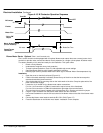
Closing C8 (Digital Input 3) selects Torque Command Mode by enabling the IDMD Isolate input (Current Loop Block).
Opening C8 selects Speed Command Mode by disabling the IDMD Isolate input.
In all cases this analog command channel bypasses the Ramps Block.
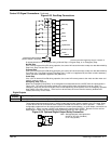
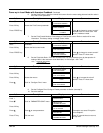
A4 Analog Input 3. ±10V analog input speed or torque reference with Accel/Decel ramps.
By closing the Reverse input at C5, the direction of the unipolar command can changed. Output of Ramps block is
connected to Setpoint 1 of the Speed Loop block. Various voltage range, and bipolar or unipolar commands can be
accepted by adjusting Calibration, Max Value, and Min Value parameters of Analog Input 3.
A5 Analog Input 4. Optional Negative Current Clamp. Inactive until Bipolar Clamps parameter is set to Enable. When
enabled, this input is the value of the negative current limit.
A6 Analog Input 5. External Current Limit / Optional Positive Current Clamp. A jumper is supplied from B3 (+10V Ref) to
A5 to allow full rated 150% current. When Bipolar Clamps parameter is set to Disabled, this input is the main current
limit value. When Bipolar Clamps parameter is set to Enable, this input value is the positive or
forward current limit.
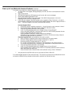
Note: The settings for AnIn1 – AnIn5 are factory set but can be changed to suit your application.
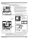
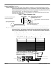
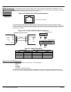
Speed Setpoint
The speed demand signal can be generated using an external 10K potentiometer as shown in Figure 4-21. The wiper is the
speed reference.
Figure 4-21 Analog Inputs
Analog GND
Analog Input
Pot Reference
Command Pot
0-20 mA or
4-20 mA Input
10KW
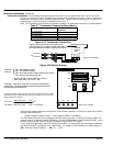
See Recommended Tightening Torques in Section 9.
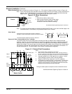
A2
500
Control
A1
AnIn1
0V
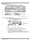
A4
Control
A1
AnIn3
0V
B3 +10VDC
A3
Control
A1
AnIn2 Speed Setpoint 1 (Non-Ramped)
0V
A4 AnIn3 Speed Setpoint 2 (Ramped)
Setpoint Ramp Input
Multiple Speed Setpoints
0–10VDC or ±10VDC Input
0–10VDC or ±10VDC Input
Control I/O
Connectors
0V 1
AnIn 1 2
AnIn 2 3
AnIn 3 4
AnIn 4 5
AnIn 5 6
AnOut 1 7
AnOut 2 8
Arm I Fbk 9
0V 1
Not Used 2
+10V Ref 3
-10V Ref 4
DigOut 1 5
DigOut 2 6
DigOut 3 7
Prog Stop 8
Coast Stop 9
0V 1
Ext Trip 2
Start 3
DigOut E 4
DigOut R 5
DigIn 1 6
DigIn 2 7
DigIn 3 8
+24V 9
AB
C