


6-26 Programming MN792
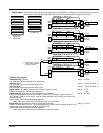
Field Control
This function block contains all the parameters for the field operating mode. It is viewed at the keypad in three
submenus. In the Field Control menu, you select the field operating mode: open loop voltage control or closed
loop current control.
In certain DC motor applications, high speeds can only be achieved by reducing the field current (torque). This
is the constant horsepower region or field weakening region, and the speed at which it begins is known as the
Base Speed.
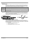
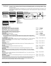
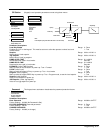
1 SETUP PARAMETERS
2 FIELD CONTROL
Field Enable
Field Control Mode
Field Quench Delay
Field Quench Mode
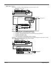
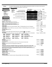
1 SETUP PARAMETERS
2 FIELD CONTROL
3 FLD CURRENT VARS
4 FLD WEAK VARS
Field Weak Enable
EMF Lead
EMF Lag
EMF Gain
Min Field Current
MAX Volts
BEMF Feedback Lead
BEMF Feedback Lag
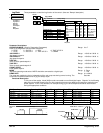
1 SETUP PARAMETERS
2 FIELD CONTROL
3 FLD VOLTAGE VARS
Field Volts Ratio
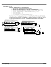
1 SETUP PARAMETERS
2 FIELD CONTROL
3 FLD CURRENT VARS
Setpoint
PROP Gain
INT Gain
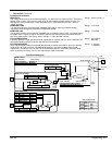
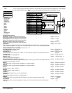
1 CONFIGURE DRIVE
Field Control Mode
Field Volts Ratio
Field Weak VARS
-
+
PID
Max
Volts
Back EMF Feedback
Field
Demand
Field Current VARS
-
+
PI
Field 1
Feedback
Firing
Angle
Field Control
Volts Ratio
Drive
Run
Phase Angle
Control
Parameter Descriptions
Field Enabled (Read in Diagnostics Parameters)
Refer to the diagnostics function block description.
Range: 0 : Disabled
1 : Enabled
Field Demand (Read in Diagnostics Parameters)
Refer to the diagnostics function block description.
Range: xxx.xx %
Field Firing Angle (Read in Diagnostics Parameters)
Refer to the diagnostics function block description.
Range: xxx.xx DEG
Field Enable
Unquenches Field Current Loop.
Range: 0 : Disabled
1 : Enabled
Field Control Mode Two modes are avaiable
(a) Field Voltage Control is an open loop phase angle control to give a certain voltage output.
(b) Field Current Control is a closed loop current control for accurate field control or expansion to field
weakening.
Range: 0 : Voltage Control
1 : Current Control
Field Volts Ratio (Ratio Out/In)
This parameter controls the output voltage from the open loop voltage control. The ratio is defined
as the dc output voltage over the ac rms input voltage. The factory setting is equivalent to a
single–phase diode rectifier.
Range: 0.00 to 100.00 % (h)
Setpoint
Field Current Setpoint.
Range: 0.00 to 100.00 %
PROP. Gain
This is the proportional gain adjustment of the field current pi loop. The factory setting of 0.10 is
equivalent to a real gain of 10.
Range: 0.00 to 100.00 %
INT. Gain
This is the integral gain adjustment of the field current PI loop.
Range: 0.00 to 100.00 %
Field Weak Enable
Activates the additional motor back emf PID loop for field weakening (field spillover) control.
Range: 0 : Disabled
1 : Enabled
EMF LEAD
With field weakening control enabled, a PID loop is brought into operation. This is the lead time
constant adjustment of the field weakening PID loop. For a value of 2.00, the real time constant =
200ms.
Range: 0.10 to 50.00
EMF LAG
This is the lag time constant adjustment of the field weakening PID loop. For a value of 4.00, the
real time constant = 4000ms.
Range: 0.00 to 200.00
EMF GAIN
This is the gain adjustment of the field weakening PID loop. For a value of 3.00, the real gain = 30.
Range: 0.00 to 100.00
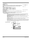
MIN FIELD CURRENT
The field weakening loop reduces the field current to achieve speed control above base speed. At
top speed the field reaches a minimum value. The Min Fld Current should be set below this
minimum value to allow reasonable margin for transient control near the top speed but not lower
than 6% as this could then cause the “Field Fail” alarm to operate.
Range: 0.00 to 100.00 %