


CE Guidelines A-3MN792
EMC Installation Instructions
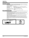
To ensure electromagnetic compatibility (EMC), the following installation instructions should be completed.
These steps help to reduce interference.
Consider the following:
• Grounding of all system elements to a central ground point
• Shielding of all cables and signal wires
• Filtering of power lines
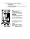
A proper enclosure should have the following characteristics:
A) All metal conducting parts of the enclosure must be electrically connected to the back plane. These
connections should be made with a grounding strap from each element to a central grounding point .
B) Keep the power wiring (motor and power cable) and control wiring separated. If these wires must
cross, be sure they cross at 90 degrees to minimize noise due to induction.
C) The shield connections of the signal and power cables should be connected to the screen rails or
clamps. The screen rails or clamps should be conductive clamps fastened to the cabinet.
D) The cable to the regeneration resistor must be shielded. The shield must be connected to ground at
both ends.
E) The location of the AC mains filter has to be situated close to the drive so the AC power wires are as
short as possible.
F) Wires inside the enclosure should be placed as close as possible to conducting metal, cabinet walls
and plates. It is advised to terminate unused wires to chassis ground.
G) To reduce ground current, use at least a 10mm
2
(6 AWG) solid wire for ground connections.
Grounding in general describes all metal parts which can be connected to a protective conductor, e.g. housing of
cabinet, motor housing, etc. to a central ground point. This central ground point is then connected to the main plant
(or building) ground.
Or run as twisted pair at minimum.
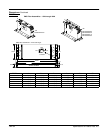
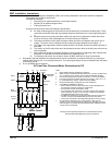
AC Line Filter, Choke and Motor Connections for CE
L1 L2 L3
L1 L2 L3
Protective
Earth
Note 2
Baldor Control
Note 1
Notes:
1. See Protection Device description in Section 4.
2. Metal conduit or shielded cable should be used. Connect conduits so the
use of a Reactor or RC Device does not interrupt EMI/RFI shielding.
3. Use the same gauge wire for Earth as used for L1, L2, L3 connections.
4. Use same gauge wire for Earth ground as is used for L and N, or L1, L2
L3. (VDE (Germany) requires 10mm
2
minimum, 6AWG).
5. Reference EMC wiring in Appendix A for CE compliance.
6. For EN60204 installations in Europe:
S Each conductor used for earth connections must individually meet
the protective earth (PE) conductor requirements.
S AC Line Filter must be connected to earth.
S For permanent earth connection, the control requires two protective
earth conductors (10mm
2
) or one (10mm
2
) conductor connected to
the independent PE point near the control.
S The Motor PE conductor is run with the motor wires and in the same
conduit. Connect to the independent PE point near the control.
S Connect the control PE to the independent PE point near the control.
7. AC Contactor is internal for size 1 and 2 controls. Size 3–5, the
contactor can be connected between TB3–3 (line) and TB3–4 (neutral)
and its purpose is to provide AC power disconnection. Maximum inrush
current must not exceed 3A.
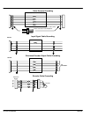
Note 3 & 4
High
Speed
Fuses
Start
Contactor
TB1
3
RE
4
TB3
This figure shows optional components not furnished with control.
Note 7
See Recommended Tightening Torques in Section 9.
AC Line
Choke
AC Line Filter
Note 6
Independent
PE Point
Armature
Field
F– F+
+
+
A+ A–