


Receiving & Installation 4-13MN792
Electrical Installation Continued
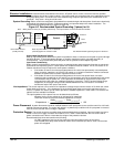
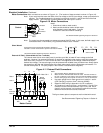
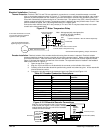
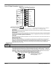
Thermal Protection Terminals TB3 TH1 and TH2 are available for connection to a normally closed thermostat or overload
relay in all operating modes as shown in Figure 4-17. The thermostat or overload relay should be a dry contact
type with no power available from the contact. If the motor thermostat or overload relay activates (opens), the
control will automatically shut down and give an Thermistor fault. The optional relay (CR1) shown provides the
isolation required and the N.O. contact is closed when power is applied to the relay and the motor is cold. If the
motor thermostat is tripped, CR1 is de-energized and the N.O. contact opens.
Connect the motor thermal wires (N.O. relay contact) to TH1 and TH2. Do not place these wires in the same
conduit as the motor power leads.
Figure 4-17 Motor Temperature Relay
* Motor
TH1
TH2
TB3
Thermostat
Do not run these wires in same conduit
as motor leads or AC power wiring.
Customer Provided
Source Voltage
Motor Thermostat Leads
CR1
*
* Optional hardware. Must be ordered separately.
Note: Add appropriately rated protective
device for AC relay (snubber)
or DC relay (diode).
See recommended terminal
tightening torques in Section 9.
If the motor thermostat is not used,
TH1 and TH2 must be jumpered
together to allow operation.
See Recommended Tightening Torques in Section 9.
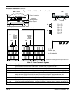
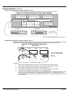
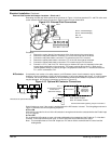
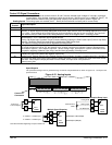
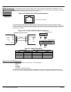
Encoder Installation Electrical isolation of the encoder shaft and housing from the motor is required. Electrical isolation
prevents capacitive coupling of motor noise that will corrupt the encoder signals. Baldor provides shielded wire
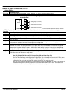
for encoder connection. Table 4-6 defines the encoder connections to the encoder receiver expansion board.
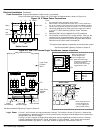
Figure 4-18 shows the electrical connections of the encoder. The expansion board is installed in the feedback
EXB location shown in Figure 4-2.
1. Open the top cover (Figure 4-1).
2. Align the 10 pin connector on the board with the connector on the left side of the control.
3. Carefully push the encoder board into position being careful not to bend any pins. All four stand–offs
should contact the control.
4. Connect the encoder wires to the expansion board, see Table 4-6 and Figure 4-18.
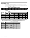
Table 4-6 Encoder Connection Descriptions
Description Encoder Connector
No.
Encoder Receiver
Board Pin.
A A 3
A A 4
B B 5
B B 6
C C
C C
+VCC Supply +VCC Supply 2
Not used (VCC Sensor) Not used (VCC Sensor)
0VDC 0VDC 1
Not used (0VDC Sensor)
Cable Shield
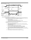
Figure 4-18 Differential Encoder Connections
Encoder
Expansion
Board
0VDC (Isolated)
+VCC (Isolated)
Channel A
Channel A
Channel B
Channel B
Torque to 3.5 lb-in (0.4Nm)
To Encoder
Align the 10 pin connector to the 10 pin connector
of the control (see Figure 4-2 for location). Carefully
seat the board onto the pins until all four standoffs
contact the control surface.
Potentiometer (VCC Adjust)
16-22AWG
Encoder Case