


4-10 Receiving & Installation MN792
Electrical Installation Continued
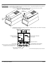
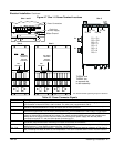
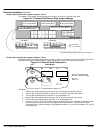
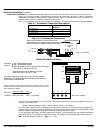
External Field Terminal and Jumper Locations – Size 2
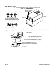
The position of the jumper selects the board to use either an internal or external motor field.
Figure 4-12 External Field Sensor Plug Jumper Settings
Jumper selecting external field supply Jumper selecting internal field supply
Connection
No Connection
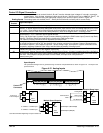
L1 L2
Field Bridge
FL1 FL2
L1 L2
Field Bridge
FL1 FL2
Terminal Board
FL1 FL2 F+ F– M1 M2 M3
External Field Selector Plug
PLG1 to Power Board PLG2 to Power Board PLG3 to Power Board
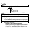
Motor Vent Fan Circuit Breaker
L N 3 4 TH1 TH2
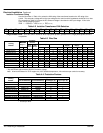
See Recommended Tightening Torques in Section 9.
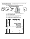
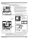
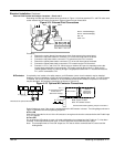
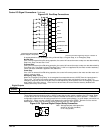
External Field Terminal and Jumper Locations – Size 3
Relocating the Red and Yellow phase wires (as shown in Figure 4-13) allows terminals D1 and D2 on the Power
Board to be used as the external field AC supply connections. External fuse must not exceed 10A.
Figure 4-13 External Field Connections
D1
D2
D3
D4
F8
F16
F18
F19
Yellow
Red
Power Board
F8 & F16 = Internal Field Supply.
F18 & F19 = External Field Supply.
Red = FL1
Yellow = FL2
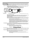
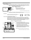
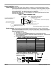
Procedure:
1. Remove the control board (2 screws secure it) to allow access to the power board.
2. Remove the red phase lead from connector “F16” on the left–hand side of the board.
3. Connect the red phase lead to connector “F19” located below D1.
4. Remove the yellow phase lead to connector “F8” on the left–hand side of the board.
5. Connect the yellow phase lead to connector “F18” located below D2.
6. Connect L1 to D1, and L2 to D2. When using an external AC input it is important to have the correct
phase relationship on the terminals. The supply must be derived from L1 (Red) and L2 (Yellow)
phases directly or indirectly through a single phase transformer. L1 must be connected to D1, and L2
connected to D2.