


Programming 6-3MN792
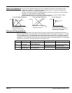
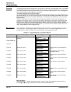
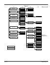
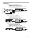
Figure 6-1
1234
Diagnostics
Setup Parameters
Password
Alarm Status
Menus
Menu Levels
Serial Links
System
Configure Drive
Parameter Save
Full & Reduced Views
Full View Only
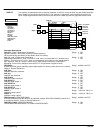
Ramps
AUX I/O
OP Station
Raise / Lower
Jog / Slack
Special Blocks
Setup
Local Ramp
Startup Values
PID
FLD Voltage VARS
FLS Current VARSCurrent Profile
Field Control
FLD Weak VARS
Stop Rates
Calibration
Inhibit Alarms
Current Loop
Speed Loop
Standstill
Setpoint Sum 1
TEC Option
System Port (P3)
Advanced
Setpoints
Adaption
Zero SPD Quench
Software
Configure I/O
Peek
5703 Support
Bisynch SupportP3 Setup
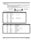
Analog Inputs
ANIN1 (A2)
ANIN2 (A3)
ANIN3 (A4)
ANIN4 (A5)
ANIN5 (A6)
Analog Outputs ANOUT1 (A7)
ANOUT2 (A8)
Digital Inputs Digital Input (C4)
Digital Input (C5)
DIGIN1 (C6)
ANOUT3 (A9)
Armature Current is
not displayed in menu
DIGIN3 (C8)
DIGIN2 (C7)
Digital Outputs DIGOUT1 (B5)
DIGOUT3 (B7)
DIGOUT2 (B6)Configure 5703
Block Diagram
Internal Links Link 1
Link 10
Configure Enable