


Receiving & Installation 4-17MN792
Control I/O Signal Connections Continued
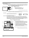
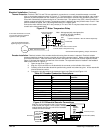
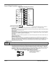
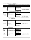
Figure 4-23 Run/Stop Connections
See Recommended Tightening Torques in Section 9.
B8 Program Stop
B9 Coast Stop
C4
Control
C3
Enable
C5 Reverse
Start
C9
+24VDC
RE
Emergency Stop Relay (Optional)
(Shown in energized - Run position)
C7
C6
Jog/Slack Mode
C8 Speed/Torque Select
Jog/Slack
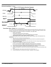
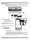
A regenerative drive can be stopped using a Normal Stop, a Program Stop, or an Emergency Stop.
Normal Stop
If the +24V is removed from C3 during operation, the control will cause the motor to stop at a rate determined by
Stop Limit, Stop Time and Curr. Limit.
Program Stop
If the +24V is removed from B8 during operation, the control will cause the motor to stop at a rate determined by
Prog Stop I Lim, Prog Stop Limit and Prog Stop Time. If +24V is re–applied to B8, the motor remains stationary
until a new Start command is applied to C3 (Start/Run).
Coast Stop
If the +24V is removed from B9 during operation, the control will remove power to the motor and the motor and
load will coast to a stop.
Emergency Stop (Optional)
When the “Emergency Stop Relay” is de–energized its contacts disconnect +24VDC from the inputs shown in
Figure 4-23. The control will remove power to the motor and the motor and load will coast to a stop. The
emergency stop relay should not be part of the normal sequencing of the system, but is an emergency operation
when safety is the main concern. If the load is to be serviced, the control must be securely disabled and
isolated, do not rely on this mode.
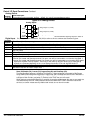
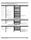
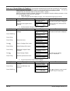
Digital Outputs
Connector
Terminal
Signal Description
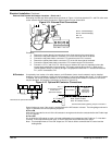
B5, B6, B7 Three digital outputs are available, DigOut1 – DigOut3. B1 is the 0V common reference point.
These digital output terminals provide a +24VDC output signal under certain conditions. An LED, Lamp, Relay
or other device can be connected at these outputs to indicate the condition of control operation. These are
configurable outputs and can be used as required in the control system design, i.e. panel lamps, connection to a
suitable PLC. Simply connect a 24VDC relay between the output and B1 (0VDC). Be sure to use a reverse
biased diode or other noise elimination device across the relay coil, see Figure 4-24.
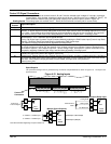
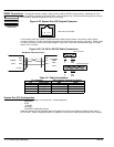
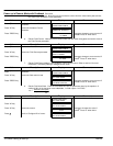
Figure 4-24 Optional Digital Output Relay Connection
CR1
Note: Add appropriately rated protective
device for AC relay (snubber)
or DC relay (diode).
B5
B1