


5-10 Switch Setting & Start-Up MN792
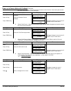
e. Is the FLD CTRL Mode parameter set to Voltage Control or Current Control?
If set to Voltage Control, check the value of the FLD. Volts Ratio parameter. Set this to 65% to
obtain 300V fields from 460V lines.
If set to Current Control, check the field current calibration set–up, refer to “Calibration”.
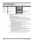
22. Verify that the OK and STOP LEDs are On, also either the FWD or REV LED. Note that all external
interlocks that affect the Enable input C4 will affect the operation of the drive. Verify their connections
and operation.
23. If the Setup Parameters::Standstill::Standstill Logic parameter is Enabled, temporarily set it to
Disabled.
Be ready to stop the control should the motor try to over speed.
24. Set the Speed Setpoints so that the value of the Speed Setpoint is 5%, 0.5V at setpoint input.
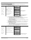
25. Set Configure Dive::Configure Enable parameter to Enable.
26. Set the SPEED FBK SELECT parameter to ARM VOLTS FBK (because it is hard–wired and
therefore the sign will be correct).
27. Slowly increase the MAIN CURR.LIMIT parameter to a maximum of 20%. The motor should begin to
rotate if all connections are made correctly. The motor speed will settle at 5% of full speed if the
motor is unloaded. Check the feedback from the Tach or Encoder using the appropriate Diagnostic
menu.
If the motor does not rotate, check the Current Feedback parameter to verify that current is flowing
into the armature. If no current is flowing, disconnect all power and check the armature connections.
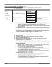
28. Stop the drive. Restore the correct Speed FBK Select parameter (if other than ARM Volts FBK) and
perform the same test again.
29. If the test was successful perform a Parameter Save and continue with step 31.
If just direction of rotation is wrong, perform a or b “Reversed Connections”.
a. Reversed Connections – Analog Tachometer:
Open the main contactor and switch off all supplies, then correct the connections.
S If the motor rotates in the correct direction, reverse the tachometer connections only.
S If the motor rotates in the wrong direction, reverse the field connections only.
If the motor still runs out of control, check the tachometer and the wiring continuity.
b. Reversed Connections – Encoder
Open the main contactor.
S If the motor rotates in the correct direction, change the Configure Drive::Encoder Sign
parameter.
S If the motor rotates in the wrong direction, disconnect all power to the Control then reverse the
field connections only.
c. Apply power (logic power then 3 phase power) and repeat step 29.
d. If the drive trips on speed feedback alarm with tachometer feedback of the correct polarity,
check the armature voltage calibration. Check the SPEED FBK SELECT. This could be set
incorrectly allowing the drive to run open loop.
30. If 5% speed is exceeded and the motor continues to accelerate a reversed connection is implied,
decrease the MAIN CURR.LIMIT parameter to zero.
Do not continue unless the control and motor are working correctly.
If any problems were found during these steps, correct them or contact Baldor before continuing.