


6-20 Programming MN792
Diagnostics Continued
Parameter Descriptions
Digital Input C4
Enable terminal.
Range: 0 : Off
1 : On
Digital Input C5
Reverse terminal.
Range: 0 : Off
1 : On
DIGIN 1 (C6)
Jog/Slack terminal.
Range: 0 : Off
1 : On
DIGIN 2 (C7)
Jog/Slack Mode terminal.
Range: 0 : Off
1 : On
DIGIN 3 (C8)
Speed or Torque mode select terminal.
Range: 0 : Off
1 : On
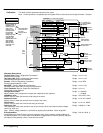
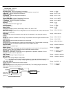
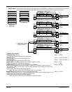
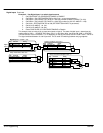
DIGOUT 1 (B5) (shown in Digital Outputs block)
At zero speed.
Range: 0 : Off
1 : On
DIGOUT 2 (B6) (shown in Digital Outputs block)
Drive healthy. Health is also displayed on the front panel LED.
Range: 0 : Off
1 : On
DIGOUT 3 (B7) (shown in Digital Outputs block)
Drive ready to run (all alarms healthy and mains synchronization achieved).
Range: 0 : Off
1 : On
Raise/Lower Output (shown in Raise/Lower block)
(OUTPUT) Value of the raise/lower ramp function.
Range: xxx.xx %
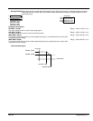
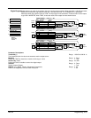
PID Output (shown in PID block)
PID block output.
Range: xxx.xx %
PID Clamped (shown in PID block)
Logic output indicating whether the PID limits are active.
Range: 0 : False
1 : True
PID Error (shown in PID block)
PID error = Input 1 – Input 2
Range: xxx.xx %
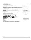
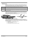
SPT Sum Output (shown in Setpoint Sum 1 block)
Setpoint sum 1 output.
Range: xxx.xx %
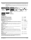
Ramp Output (shown in Ramps block)
Setpoint ramp output.
Range: xxx.xx %
Speed Setpoint (shown in Speed Loop block)
Speed loop total setpoint including the ramp output before the ramp–to–zero function.
Range: xxx.xx %
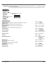
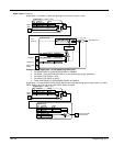
Terminal Volts (shown in Calibration block)
Scaled terminal volts.
Range: xxx.xx % (h)
Back EMF (shown in Calibration block)
Calculated motor back EMF including IR compensation.
Range: xxx.xx % (h)
UNFIL TACH Input (shown in Calibration block)
Unfiltered analog tachogenerator feedback.
Range: xxx.xx % (h)
Encoder (Diagnostics only)
Encoder speed feedback in RPM.
Range: xxxxx RPM
Raw Encoder RPM (shown in Calibration block)
Unfiltered encoder speed feedback in RPM.
Range: xxxxx RPM
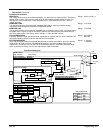
UNFIL Speed FBK (shown in Speed Loop block)
Unfiltered speed feedback.
Range: xxx.xx %
UNFIL Speed Error (shown in Speed Loop block)
Unfiltered speed error.
Range: xxx.xx %
Contactor Closed (Diagnostics only)
Main contactor control signal.
Range: 0 : Off
1 : On
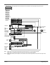
HEALTH LED (shown in Alarms block)
State of Health LED on Operator Station.
Range: 0 : False
1 : True
READY (shown in Alarms block)
The drive is ready to accept an enable signal.
Range: 0 : False
1 : True
DRIVE RUNNING (Diagnostics only)
Drive is enabled and may make current when TRUE. A diagnostic for those parameters that can
only be written to when the drive is stopped (parameters marked with Note 2 in the Parameter
Specification Table).
Range: 0 : False
1 : True
SYSTEM RESET (Diagnostics only)
Set for one cycle as the drive is enabled.
Range: 0 : False
1 : True