


Switch Setting & Start-Up 5-9MN792
Power up in Remote Mode with Feedback Continued
14. Set the Configure Dive::Configure Enable parameter to disable (see step 9).
15. Save the settings.
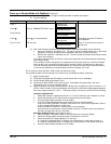
Action Description Display Comments
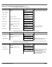
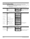
Start at Menu
Level 1
MENU LEVEL
DIAGNOSTICS
Press B
Scroll to “PARAMETER SAVE” menu.
MENU LEVEL
PARAMETER SAVE
Press “M” key
PARAMETER SAVE
UP TO ACTION
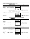
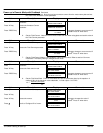
Press Y Press Y to save parameters.
PARAMETER SAVE
REQUESTED
Parameters are saved. Except the
“Local Setpoint”.
Press “E” key Exit one level
MENU LEVEL
PARAMETER SAVE
Press “E” several times to return to
the top level.
16. With +24V present at terminals B8 and B9 (Program Stop and Coast Stop), do the following:
a. Apply the “Start/Run” command to C3. The main 3–phase contactor should pull–in and remain
energized, (it may de–energize almost immediately due to the 3–phase fail alarm).
b. Remove the “Start/Run” command from C3. The main 3–phase contactor should drop–out and
remain de–energized.
If the above sequence does not function, remove the Logic power and check start/stop sequencing
and contactor wiring.
If the contactor remains energized for an extended time during this check, the controller will detect
that 3–phase is not connected and switch off the contactor, and the 3–phase alarm is displayed.
The main contactor should never be operated by any means other than the drive internal controls,
nor should any additional circuitry be placed around the contactor coil circuit.
Do not continue unless the Start / Stop circuits are working correctly.
If any problems were found during step 16, correct them or contact Baldor before continuing.
17. Apply 3 phase power.
18. Verify that the keypad and LED displays are still normal with no error messages.
19. Set the Speed Setpoint parameter to zero.
20. Verify that the Main CURR. Limit is set to 0.00%. View ANIN 5 (A6) parameter in the level 1
Diagnostics menu and verify it displays 0.00V.
21. Apply the Start/Run command and check that 3–phase mains is applied to Power Terminals L1, L2
and L3. Initiate “Enable” (C4) and immediately check that the correct field voltage appears between
the control supply terminals F+ and F–. If the field voltage is not correct, check one of the following:
Internally Supplied Field:
c. Check that 3–phase is applied to terminals L1, L2 and L3 when the main contactor is closed.
d. Check that the fuses on the power board or supression board are healthy.
e. Verify the Field Enable parameter is set to Enable.
f. Is the FLD CTRL Mode parameter set to Voltage Control or Current Control?
If set to VOLTAGE CONTROL, check the value of the FLD. VOLTS RATIO parameter. Set this
to 65% to obtain 300V fields from 460V lines.
If set to CURRENT CONTROL, check the field current calibration.
If the field volts are at maximum, check the field continuity. (The field current may initially be
less than the rated value due to a cold field.)
Externally Supplied Field: (not available for size 1)
a. Refer to Chapter 4 Installation, Motor Field Connections for conversion details.
b. Check the voltage applied (externally fused) to terminals FL1 and FL2.
c. Check the phasing of voltage applied to FL1 and FL2:
FL1 must be connected directly or indirectly to the Red phase on main power terminal L1.
FL2 must be connected directly or indirectly to the Yellow phase on main power terminal L2.
d. Verify the Field Enable parameter is set to Enable.