


1-2 Quick Start MN792
Reference and Jumpers for Remote Operation
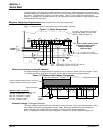
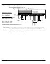
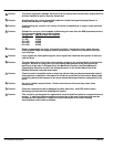
For remote operation, the speed reference and other connections are made at the terminal strip connector. Not
all of these connections are shown in Figure 1-3.
Figure 1-3 Reference and Jumper Connections
Minimum jumper connections:
A1 to A2 – 500 ohm jumper for 20mA input
A6 to B3 – Analog Input 5 = +10VDC
C4 to C9 – Enable = +24VDC
C1 to C2 – No External Trip
DH
Health Relay
PROG Stop
Coast Stop
Start
Jog
Jumper if contacts are not used:
B8 to C9 – PROG Stop = +24VDC
B9 to C9 – Coast Stop = +24VDC
The Health relay (24VDC coil) may be installed between B6 and C1
to provide fault indication to an external device or circuit.
500 ohm
Jumper for
0-20mA
0V 1
AnIn 1 2
AnIn 2 3
AnIn 3 4
AnIn 4 5
AnIn 5 6
AnOut 1 7
AnOut 2 8
Arm I Fbk 9
0V 1
Not Used 2
+10V Ref 3
-10V Ref 4
DigOut 1 5
DigOut 2 6
DigOut 3 7
Prog Stop 8
Coast Stop 9
0V 1
Ext Trip 2
Start 3
DigIn E 4
DigIn R 5
DigIn 1 6
DigIn 2 7
DigIn 3 8
+24V 9
AB
C
500
Optional Speed
Feedback Board
Signal
Connections
Speed Reference connections:
A1 – one end of Pot
B3 – one end of Pot
A4 – wiper of Pot
C1 to C2 – No External Trip
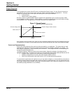
Speed Feedback The factory setting for speed feedback is Armature Voltage which does not require an optional feedback
board. If an optional board must be used, refer to its manual to install and set the board configuration.
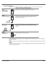
Serial Link A PC COM port may be connected to the control at the System Port (P3). At Menu Level : Serial Links, all of
the parameters can be set for your application.