


Switch Setting & Start-Up 5-11MN792
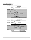
Power up in Remote Mode with Feedback Continued
Note: Reverse Operation is possible with the Series 30 REGEN Drives only.
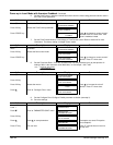
31. With the MAIN CURR.LIMIT parameter set to 20% or the level required to achieve rotation, set the
value of the Speed Setpoint to 10%, 1.0V at setpoint input. The motor will accelerate to this speed
setting.
32. Adjust the Zero Speed parameter (Ensure Standstill is Disabled).
a. Non–REGEN, non–reversing applications – Set the Speed Setpoint potentiometer to zero and
adjust the Zero Speed Offset parameter until the shaft is just rotating then reduce level until the
shaft stops.
b. REGEN, non–reversing applications – Set the Speed Setpoint potentiometer to zero and adjust
the Zero Speed Offset parameter for minimum shaft rotation. (Series 30 REGEN Drives only).
c. REGEN, reversing applications – Set the Zero Speed Offset parameter to balance maximum
speed in forward and reverse directions. (Series 30 REGEN Drives only).
You can set the Standstill Logic parameter to Enable if a stationary shaft is required.
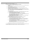
33. For reversing applications set the value of the Speed Setpoint to –10% and check that motor runs in
the reverse direction.
34. Gradually increase the Speed Setpoints so that the value of the Speed Setpoint (Diagnostic menu) is
at maximum. Verify that shaft speed is correct. If fine adjustment is required, adjust the calibration
as appropriate to the speed feedback selection:
a. Armature Voltage feedback has a +2/–10% trim, greater changes outside this range require a
change of the calibration switches.
b. Analog tachometer has a +2/–10% trim, greater changes outside this range require a change of
the calibration switches.
c. An Encoder should give an absolute rotational speed for which adjustment is unnecessary .
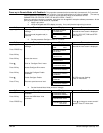
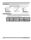
Adjustment for Field Weakening.
If the drive is to run with a top speed greater than the base speed, “field weakening” is used to achieve the top
speed. The field must be operating in Current Control mode. Select Current Control in the
Configure Drive::FLD CTRL Mode parameter.
Note: Field weakening cannot be used if you have Armature Voltage feedback selected. Adjust the maximum
armature volts to the required scaled level by setting the MAX VOLTS parameter.
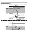
1. Operate the control at base speed and verify the motor volts are correct.
2. In the Level 4 FLD WEAK VARS menu, verify that field weakening is selected (FIELD WEAK
ENABLE) and that the MIN FLD CURRENT parameter is set appropriately.
3. Increase the speed above the base speed. Verify that the armature volts remain constant while the
field current reduces.
4. Gradually increase to maximum speed. Monitor the armature volts at maximum speed. If necessary,
trim the speed feedback as previously detailed in Step 34 a, b or c.
5. Adjust the MIN FLD CURRENT parameter to the appropriate setting to limit maximum motor speed.
PROCEED WITH CARE – Make Small Adjustments.
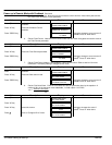
6. IR COMPENSATION (CALIBRATION function block) is also used in field weakening applications to
improve dynamic response and speed holding stability. Set the IR Compensation as follows
a. Set Field Enable to Disabled (Field Control function block).
b. Start the drive with a 5% speed command and ensure the ACTUAL POS I LIMIT is 100%
(diagnostic). This should stall the drive at zero speed and cause it to pass 100% current.
c. Monitor the BACK EMF diagnostic parameter and note the value (typically anything up to 17%
is normal).
d. Stop the drive and enter this value into IR Compensation parameter and repeat the test to
ensure that Back EMF is now zero.
e. Set Field Enable parameter to Enabled.
7. For reversing drives, check the maximum reverse speed. Imbalance in reversing applications can
only be corrected by adjusting the ZERO SPD OFFSET parameter, which may be to the detriment of
operation at Zero Setpoint.