


Programming 6-5MN792
Analog Inputs Continued
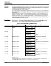
Input Description
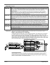
Analog input 1
Terminal (A2)
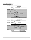
Used as a unipolar 0–20mA ramped speed command channel. Output [246] is connected to Setpoint Sum 1,
Input 1. To use 4–20mA requires setting the Min value to 25%, the Max Value to 125% and the Setpoint Sum1,
Input 2 to (–)25%. These settings provide the proper scaling and offset to set 4mA to zero command. An input
value less than 4mA results in a Min Value of 25% being summed with the (–)25% at the Setpoint Sum 1
summing junction.
Output of Setpoint Sum 1 block is connected to the ramp input [5] of the Ramps block. Ramp invert [620] is
controlled by C5, the reverse input. When C5 is closed, the ramp is inverted and the rotation direction is
changed. This allows an Accel and Decel Rate limited command signal in either direction. Output of Ramps
block is connected to Setpoint 1 of the Speed Loop block.
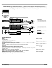
Analog input 2
Terminal (A3)
No Accel / Decel Ramp is provided for this input.
Used as a non–ramped speed or torque command channel. Output [493] is connected to Speed Loop Setpoint 2
and Current Loop Input. Closing terminal C8 (Digital Input 3) selects Torque Command Mode (enables IDMD
Isolate input of the Current Loop). Opening terminal C8 (Digital Input 3) selects Speed Command Mode by
(disables the IDMD Isolate input of the Current Loop). In all cases this analog command channel bypasses the
Ramps Block.
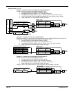
Analog input 3
Terminal (A4)
Used as a ramped ±10V speed command channel. Output [249] is connected to Setpoint Sum 1, Input 0.
Output of Setpoint Sum 1 block is connected to the ramp input [5] of the Ramps block. Ramp invert [620] is
controlled by C5, the reverse input. When C5 is closed, the ramp is inverted and the rotation direction is
changed. This allows an Accel and Decel Rate limited command signal in either direction. Output of Ramps
block is connected to Setpoint 1 of the Speed Loop block. Various voltage range, and bipolar or unipolar
commands can be accepted by adjusting Calibration, Max Value , and Min Value parameters of Analog Input 3.
Analog input 4
Terminal (A5)
Not active if Bipolar Clamps parameter [90] is false.
Used as an External Reverse (Negative) Current Limit if Bipolar Clamps parameter [90] is true.
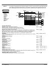
Analog input 5
Terminal (A6)
Used as an External (Forward and Reverse) Current Limit. A hardwire jumper is supplied from terminal B3
(+10V Ref) to A5 to allow full rated 150% current. Used as an External Forward Current Limit if Bipolar Clamps
parameter is set to Enabled.
When [90]=False, Analog IN 5 provides a bipolar current limit.
When [90]=True, Analog IN 5 is the positive current limit (Analog IN 4 is the negative current limit).
Analog Inputs – Inputs can be connected to any writable parameter. The read/write status of each parameter is listed in
Appendix B. (RO is read only and RW is read/write.)
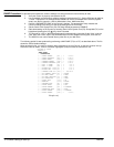
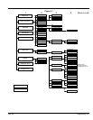
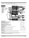
Example – Using analog input 1 as a 4–20mA input.
The parameter values for Analog Input 1 can be changed at the keypad. The 4–20mA source is connected to
A2. Apply AC power to the control and observe the keypad display. The 500 ohm resistor at the A2 input
converts a 0–20mA input current to 0 to 10 volt signal. So a 4–20mA input must be scaled so 4mA = 0VDC and
20mA = 10VDC. Analog Input 1 output terminal [246] is connected to Setpoint Sum 1, Input 1. 4–20mA
requires the Min value = 25%, Max Value = 125% and setting Setpoint Sum1, Input 2 to (–)25%. These settings
provide the proper scaling and offset to set 4mA to zero command. Any input less than 4mA will result in a Min
Value of 25% being added to (–)25% at the Setpoint Sum 1 summing junction.
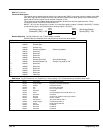
[208] Ratio 0 1.0000
[309] Input 0 0.00%
[292] Sign 0 Positive
Tag Parameter
Setup Parameters::Setpoint Sum 1::
[423] Input 2 -25.00%
[6] Ratio 1 1.0000
[420] Divider 0 1.0000
A
B
A
B
+
-
[100] Input 1 0.00%
+
+
+
[419] Divider 1
1.0000
[8] Sign 1 Positive
[131] Deadband Width
0.0%
[375] Limit
105.00%
[86] Destination Tag 5
+
-
[231] Max Value 125.00%
[230] Calibration 1.0000
Tag Parameter Setting
[232] Min Value
25.00%
[246] Destination Tag 100
Analog
Input 1
[246]
A2
Analog Input 1 – ANIN 1 (A2)
[86]
Setting
500
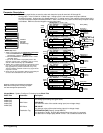
4–20mA Direction Change
Output of Setpoint Sum 1 block is connected to the ramp input [5] of the Ramps block. Ramp invert [620] is
controlled by C5, the reverse input. When C5 is closed, the ramp is inverted and the rotation direction is
changed. This allows an Accel and Decel Rate limited command signal in either direction. Output of Ramps
block is connected to Setpoint 1 of the Speed Loop block.