


6-12 Programming MN792
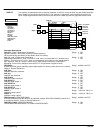
Calibration
This block contains parameters specific to the motor.
Note: Control operation is suspended and all Keypad LEDs will flash while the Configure Enable = Enabled.
1 SETUP PARAMETERS
2 CALIBRATION
Configure Enable
NOM Motor Volts
Armature Current
Field Current
Armature V CAL
IR Compensation
Encoder RPM
Encoder Lines
Analog TACH CAL
Zero SPD Offset
Armature I (A9)
SPDFBK Alarm Level
Stall Threshold
Stall Trip Delay
REM Trip Delay
Overspeed Level
Field I CAL
These parameters
can also be set in
the Level 1
Configure Drive"
menu.
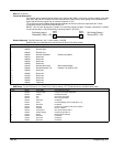
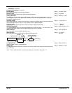
[24] Encoder Lines
1000
[22] Encoder RPM 1000 RPM
Tag Parameter
Factory Setting
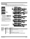
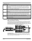
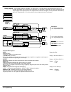
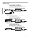
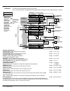
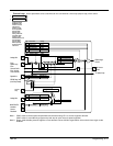
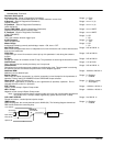
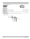
Calibration – Functional Diagram
[23] Analog TACH CAL
1.0000
[10] Zero SPD Offset
0.00%
Encoder
Expasnion Board
Encoder
Tachometer
Expansion Board
TACH
Diagnostic
connections
[59] [206]
[20] Armature V CAL
1.0000
VA
Terminal Volts
[521] NOM Motor Volts
100 Volts
[21] IR Compensation
0.00%
Armature
ACCT
To Speed Loop
Speed Feedback
Selection
[180] SPDFBK ALM Level
50.0%
[523] Armature Current
2.0 Amps
[60]
To Field
Regulator
Diagnostic
connection
Speed Feedback
From Speed Loop
Speed Feedback Alarm
To Inhibit Alarms
[224] Stall Trip Delay
10.0 Sec
[263] Stall Threshold
95.00%
t
[112]
Stall Trip
To Inhibit Alarms
At Zero Speed
From Standstill
[25] Armature I (A9)
Bipolar
ABS
Armature Current
0-10V or ±10V
[A9]
[182] Field I CAL
1.0000
Field
ACCT
[524] Field Current
4.0 Amps
Diagnostic
connections
[59] [206]
Field I FBK
BEMF
From
Power
Board
CAL Circuit
Parameter Descriptions
Terminal Volts (Read in Diagnostics Parameters)
Scaled terminal voltage.
Range: xxx.xx % (h)
Tach Input (B2) (Read in Diagnostics Parameters)
Scaled analog tachogenerator feedback.
Range: xxx.xx % (h)
Encoder (Read in Diagnostics Parameters)
Encoder speed feedback in RPM
Range: xxxxx RPM
Back EMF (Read in Diagnostics Parameters)
Calculated motor back EMF including IR compensation.
Range: xxx.xx % (h)
Field I Feedback (Read in Diagnostics Parameters)
Scaled field current feedback
Range: xxx.xx %
Configuration Enable
When enabled, allow configuration changes but suspends control operation.
Range: 0 : Disabled
1 : Enabled
NOM Motor Volts
Set this value to match the armature volts rating of the motor.
Range: 100 to 875 Volts
Armature Current
Set this value to match the armature current rating of the motor.
Range: 2.0 to 15.0 AMPS
Field Current
Set this value to match the Field Current rating of the motor.
Range: 0.2 to 4.0 AMPS
Armature V CAL
Trim adjustment of the motor armature volts to give exactly 100% at the required actual voltage
value (e.g. 460V etc.).
Note: Primary voltage calibration is achieved by adjusting VA calibration values using SW7.
Range: 0.9800 to 1.1000
IR Compensation
Compensation for motor IR drop to improve regulation when using armature voltage feedback as
the speed feedback. This is also used in field weakening applications to improve dynamic response
and speed holding stability, refer to “initial start–up routine”.
Range: 0.00 to 100.00 %