


Receiving & Installation 4-7MN792
Electrical Installation Continued
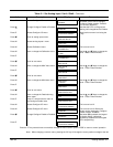
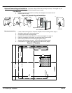
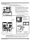
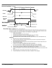
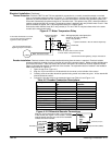
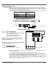
Figure 4-7 Size 1–5 Power Terminal Locations
Power Connections
Motor Ground
Earth from
AC Main Supply
Size 1 and 2 Size 3
A+
A–
L1 L2 L3
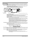
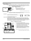
Size 4
L1 L2 L3
A+
A-
Field
Connections
Logic Supply,
Contactor &
Thermistor
Connections
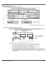
Size 5
L1 L2 L3
A+
A+
Field
Connections
Logic Supply,
Contactor &
Thermistor
Connections
L1 L2 L3
A-
A-
See Recommended Tightening Torques in Section 9.
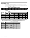
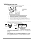
D1, D2
D3, D4
D5, D6
D7, D8
D1 = FL1
D2 = FL2
D3 = F–
D4 = F+
D5 = 3
D6 = 4
D7 = N
D8 = L
THERM+ and
THERM– are
on separate bd.
in door assembly
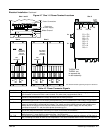
Table 4-5 Power Connector Signals
Terminal Description
L1, L2, L3 Main AC input power. A 3–phase AC contactor should be connected in the main AC power supply connections.
(AC Contactor is internal for Size 1 and 2 controls. For other sizes, use terminals 3 and 4).
A+, A– The motor armature is connected to busbar terminals A+ and A–. If a DC contactor is used the contactor poles
should be interposed between the control terminals and the motor terminals.
F+, F– Connect the motor field (–) to terminal F– and field (+) to terminal F+. If the motor has no field connections, is a
permanent magnet motor, or if the field is derived externally, you must disable the Field Enable [170] parameter.
FL1, FL2 An external field supply may be used for Size 2–5 controls. Connect this supply to terminals FL1 and FL2. The
voltage is determined by the desired field voltage. The supply must be protected externally with suitable fuses.
Always derive the supply from the Red and Yellow phases of the main power supply, with the Red phase
connected to terminal FL1 and the Yellow phase connected to FL2.
3, 4 Size 3–5, the AC Contactor coil can be connected between TB3–3 (line) and TB3–4 (neutral) and its purpose is to
provide AC power disconnection. Maximum coil inrush current must not exceed 3A.
L, N Single phase AC power for logic circuits. The auxiliary supply must be connected directly to the incoming supply,
(disconnect only). (Logic Supply is internal for Size 1 and 2 controls).
TH1, TH2 Connection for motor thermal protection. Thermistors must have a combined working resistance of 750 ohms or
less, increasing to at least 4k ohms at over–temperature. The alarm is latched and the contol must be restarted.