


6-6 Programming MN792
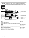
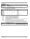
Analog Outputs
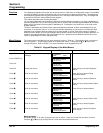
Three Analog Outputs are available, A7, A8 and A9. A7 and A8 can be configured and the source of an
analog output signal can be read from any parameter. It is important to remember that other parameters do not
“send” signals to the output terminal. An output terminal “retrieves” the signal from the parameter described by
its Source Tag parameter. A9 is the armature current output and cannot be changed.
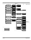
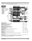
1 SYSTEM
2 CONFIGURE I/O
3 ANALOG OUTPUTS
4 ANOUT 1 (A7)
% TO GET 10V
MODULUS
OFFSET
SOURCE TAG
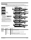
Tag Parameter
[245] % to get to 10V +100.00%
[464] Offset 0.00%
Factory Setting
[362] Modulus
False
Analog
Output 1
ANOUT 1 (A7)
[251] Source Tag[62] Speed Feedback
Speed Loop
Diagnostic
connection
62
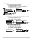
Tag Parameter
[248] % to get to 10V
+100.00%
[465] Offset 0.00%
Factory Setting
[363] Modulus False
Analog
Output 2
ANOUT 2 (A8)
[252] Source Tag[63] Speed Setpoint
Setpoints
63
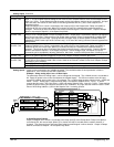
Description
+10V= Full speed setpoint forward.
-10V = Full speed setpoint reverse.
+10V= Full speed setpoint forward.
-10V = Full speed setpoint reverse.
Bipolar Mode
+10V= 200% output current forward.
-10V = 200% output current reverse.
Unipolar Mode
+10V= 200% output current.
ABS
ABS
Analog
Output 3
[25] Armature I (A9) Bipolar
UNI
Power
Board
Calibration
Board
I
Arm
ANOUT 3 (A9)
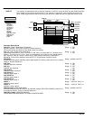
A7
A8
A9
[55]
Diagnostic
connection
[56]
Arm I Fbk
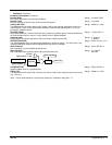
Parameter Descriptions
INPUT
(SOURCE TAG)
The source Tag No. of the output value.
Range: 0 to 549
% TO GET 10V (10V CAL)
This value is based on the range of the source. It can be set positive or negative to set the sign of
the output and scale the input to give a 10V output.
Range: –300.00 to 300.00 %
OFFSET
Offset value added to the input value after the scaler and before the modulus.
Range: –100.00 to 100.00 %
MODULUS
Modulus determines whether the output is bipolar or unipolar.
False allows the input to pass through to the output (bipolar).
When TRUE, the output is unipolar (will not go negative). Negative input values are made positive
(absolute value).
Range: 0 : False
1 : True
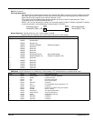
ANOUT 1 & 2 (Read in Diagnostics Parameters)
ANOUT 1 (A7)=scaled speed feedback. ANOUT 2 (A8)= Total speed setpoint.
Range: xxx.xx Volts (h)
Armature I (A9) (Armature Current only at Analog Output 3)
Bipolar provides ±10V signal that represents armature current.
Unipolar provides 0 to 10V signal that represents armature current.
Range: 0 : Bipolar
1 : Uniploar