


Receiving & Installation 4-5MN792
Electrical InstallationAll interconnection wires between the control, AC power source, motor, host control and any operator
interface stations should be in metal conduits. Use listed closed loop connectors that are of appropriate size for
wire gauge being used. Connectors are to be installed using crimp tool specified by the manufacturer of the
connector. Only class 1 wiring should be used.
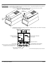
System Grounding Baldor controls are designed to be powered from standard single and three phase lines that are electrically
symmetrical with respect to ground. System grounding is an important step in the overall installation. The
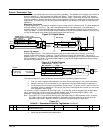
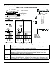
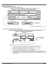
recommended grounding method is shown in Figure 4-6.
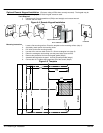
Figure 4-6 Recommended System Grounding (3 phase) for UL
AC
Supply
(Mains)
Driven Earth Ground
(Facility Ground)
Four Wire “Wye”
L1
L2
L3
Earth
Route all power wires L1, L2, L3 and Earth
(Ground) together in conduit or cable.
Note: Wiring shown for clarity of grounding method only. Not representative of actual terminal block location.
Disconnect
and Fuses
L1
L2
L3
Control
A+
A–
F+
F–
TH1
TH2
Armature
Field
Thermistor
+
+
Motor
GND
See Recommended Tightening Torques in Section 9.
Ungrounded Distribution System
With an ungrounded power distribution system it is possible to have a continuous current path to ground through
the MOV devices. To avoid equipment damage, an isolation transformer with a grounded secondary is
recommended. This provides three phase AC power that is symmetrical with respect to ground.
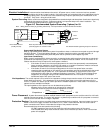
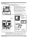
Input Power Conditioning
Baldor controls are designed for direct connection to standard single and three phase lines that are electrically
symmetrical with respect to ground. Certain power line conditions must be avoided. An AC line reactor or an
isolation transformer may be required for some power conditions.
• If the feeder or branch circuit that provides power to the control has permanently connected power
factor correction capacitors, an input AC line reactor or an isolation transformer must be connected
between the power factor correction capacitors and the control.
• If the feeder or branch circuit that provides power to the control has power factor correction
capacitors that are switched on line and off line, the capacitors must not be switched while the control
is connected to the AC power line. If the capacitors are switched on line while the control is still
connected to the AC power line, additional protection is required. TVSS (Transient Voltage Surge
Suppressor) of the proper rating must be installed between the AC line reactor or an isolation
transformer and the AC input to the control.
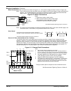
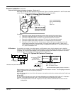
Line Impedance The control requires a 5% maximum line impedance (voltage drop across the reactor is 5% when the control
draws rated input current). If the impedance of the incoming power does not meet the requirement for the
control, a 3 phase line reactor can be used to provide the needed impedance in most cases. Line reactors are
optional and are available from Baldor.
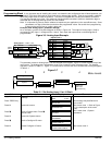
The input impedance of the power lines can be determined as follows:
Measure the line to line voltage at no load and at full rated load.
Use these measured values to calculate impedance as follows:
%Impedance +
(Volts
No Load Speed
* Volts
Full Load Speed
)
(Volts
No Load Speed
)
100
Power Disconnect A power disconnect should be installed between each input power source and the control for a fail–safe
method to disconnect power. The control will remain in a powered-up condition until all input power is removed
from the control and the internal voltage is depleted.
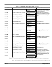
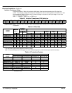
Protection Devices The control must have a suitable input power protection device installed. Input and output wire size is
based on the use of copper conductor wire rated at 75 °C. Table 4-3 describes the wire size to be used for
power connections and Table 4-4 describes the ratings of the protection devices.
Recommended fuse sizes are based on the following:
UL 508C suggests a fuse size of four times the continuous output current of the control.
Dual element, time delay fuses should be used to avoid nuisance trips due to inrush current when
power is first applied.