


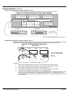

4-14 Receiving & Installation MN792
Electrical Installation Continued
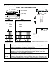
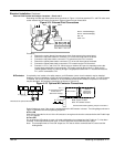
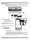
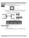
Tachometer Installation The tachometer expansion board can be used to connect either an AC Tach or a DC Tach to the
control (only one may be used). Shielded wire must be used for tachometer connection. Table 4-7 defines the
tachometer connections to the tachometer expansion board. Figure 4-19 shows the electrical connections of
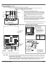
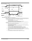
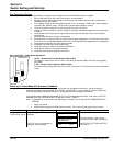
the tachometer. Figure 4-20 shows the settings for this board.
Note: DC Tachometers provide speed and direction feedback. AC tachometers provide only speed feedback.
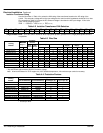
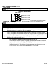
Table 4-7 Tachometer Connection Descriptions
Description Tachometer Receiver
Board Pin.
AC Tach Input 1
AC Tach Input 2
DC Tach Input + 3
DC Tach Input – (0VDC) 4
Figure 4-19 Tachometer Connections
Tachometer
Expansion
Board
Torque to 5.3 lb-in (0.6Nm)
To AC Tach
Align the 10 pin connector to the 10 pin connector of the
control (see Figure 4Ć2 for location). Carefully seat the board
onto the pins until all four standoffs contact the control surface.
To DC Tach
OR
G
1
G
2
G
3
G
4
Figure 4-20 Switch Settings
Torque to 5.3 lb-in (0.6Nm)
G1 G2 G3 G4
DC
AC
SW4
SW4
SW1
SW2
SW3
SW4
1"
10"
100"
Jumper
SW1 = Ones calibration switches.
SW2 = Tens calibration switches.
SW3 = Down adds 100 VDC in the down position (100's position).
SW4 = Up for AC Tach; Down for DC Tach.
Calibration
Switches
As shown, switches are set for 188VDC for a DC tach:
(SW3 + SW2 + SW1 = 100 + 80 + 8 = 188)
The jumper is always used. It plugs onto the control PCB in just about the
position shown. This jumper is where the actual scaled signal connects from
the Tach board to the controller PCB.
0
For full speed tach voltages greater than 200V, an external resistor of value
RE must be used in series with the DC Tach connection at G3. The value
RE is calculated as follows:
RE ohms =
(Max Tach Volts * 200)
5
kW
RE Watts = (Max Tach Volts * 200) 5 milliwatts
In general, the voltage output of an analog AC or DC tachometer generator is a function of speed and is rated in
volts per 1000 RPM so that:
Speed Feedback Voltage
Max
(volts) + Motor Speed
Max
(RPM) x Tach Rating
The Tach Rating should be on the nameplate of the tachometer generator. Fine tuning is performed within the
software (refer to the Speed Feedback Calibration). If the full speed feedback voltage exceeds 200 VDC, use an
external resistive scaling network to drop the feedback voltage to within this range.
For AC tachometer generators, the switch settings will be about 1.3 times greater than the voltage measured at
the input terminals G1 and G2 due to the rectifier offset. For example, for 90V feedback, the switch setting is:
2
Ǹ
Required Voltage Feedback + 2
Ǹ
90 + 127V
.