


6-32 Programming MN792
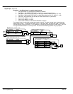
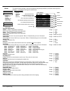
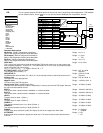
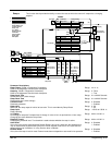
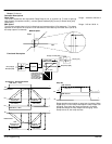
PID This is a general purpose PID block which can be used for many closed loop control applications. PID feedback
can be loadcell tension, dancer position or any other transducer feedback such as pressure, flow etc.
1 SETUP PARAMETERS
2 SPECIAL BLOCKS
3 PID
PROP Gain
INT Time CONST
Derivative TC
Positive Limit
Negative Limit
O/P Scaler (Trim)
Input 1
Input 2
Ratio 1
Ratio 2
Divider 1
Divider 2
Enable
INT Defeat
Filter TC
Mode
MIN Profile Gain
Profiled Gain
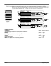
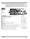
PID
[473] Mode 0
[404] PROP Gain 1
Tag Parameter
Factory Setting
[474] MIN Profile Gain 20.00%
[475] Profile Gain
[401] Derivative TC 0.000 Seconds
[402] INT Time Constant 5.00 Seconds
[403] Filter TC 0.100 Seconds
A/B
PID
[412] Ratio 1 1.0000
[410] Input 1 0.00%
[418] Divider 1 1.0000
A/B
[413] Ratio 2 1.0000
[411] Input 2 0.00%
[414] Divider 2 1.0000
-
+
[415] PID Error
[416]
PID
Clamped
[417]
PID
Output
[409] INT Defeat Off
[408] Enable Enabled
[406] Negative Limit -100.00%
[405] Positive Limit 100.00%
[407] Output Scaler (Trim) 0.2000
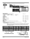
Parameter Descriptions
PID Output (Read in Diagnostics Parameters)
Refer to the diagnostics function block description.
Range: xxx.xx %
PID Clamped (Read in Diagnostics Parameters)
Refer to the diagnostics function block description.
Range: 0 : False
1 : True
PID Error (Read in Diagnostics Parameters)
Refer to the diagnostics function block description.
Range: xxx.xx %
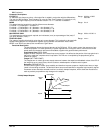
PROP. Gain
This is a pure gain factor which shifts the whole Bode PID transfer function up or down leaving the
time constants unaffected. A value of P = 10.0 means that, for an error of 5%, the proportional part
(initial step) of the PID output will be:
10 x [ 1 + (Td/Ti) ] x 5 % , i.e. approx. 50% for Td << Ti.
Range: 0.0 to 100.0
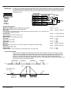
INT. TIME CONST (SPD.INT.TIME)
The integrator time constant (Ti)
Range: 0.01 to 100.00
Seconds
DERIVATIVE TC
The differentiator time constant (Td). When Td = 0 the transfer function of the block becomes a P+I.
Range: 0.000 to 10.000
Seconds
Positive Limit
The upper limit of the pid algorithm.
Range: 0.00 to 105.00 %
Negative Limit
The lower limit of the PID algorithm.
Range: –105.00 to 0.00 %
Output Scaler (Trim) (Output Scaler Gain)
The ratio which the limited PID output is multiplied by in order to give the final PID Output. Normally
this ratio would be between 0 and 1.
Range: –3.0000 to 3.0000
INPUT 1
This can be either a position/tension feedback or a reference/offset.
Range: –300.00 to 300.00 %
INPUT 2
This can be either a position/tension feedback or a reference/offset.
Range: –300.00 to 300.00 %
RATIO 1
The gain factor for Input 1 (Ratio 1).
Range: –3.0000 to 3.0000
RATIO 2
The gain factor for Input 2 (Ratio 2).
Range: –3.0000 to 3.0000
DIVIDER 1
This reduces (divides) Input 1 by a factor (Divider 1).
Range: –3.0000 to 3.0000
DIVIDER 2
This reduces (divides) Input 2 by a factor (Divider 2).
Range: –3.0000 to 3.0000
ENABLE
A digital input which resets the (total) PID Output as well as the integral term when false.
Range: 0 : Disabled
1 : Enabled
INT. DEFEAT
A digital input which resets the integral term when true. The block transfer function then becomes
P+D only.
Range: 0 : Off
1 : On