


4-6 Receiving & Installation MN792
Electrical Installation Continued
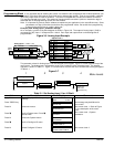
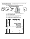
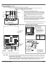
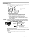
Isolation Transformer Sizing
Use the information in Table 4-2 to select the KVA rating of the transformer based on the HP rating of the
control. The secondary voltage will be the input voltage to the control and the impedance should be 2% or less.
One exception to Table 4-2 is when the DC armature voltage is less than the AC input voltage. If this is the
case, use the following formula:
KVA + 0.00163 VAC
Secondary
IDC
Secondary
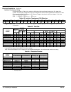
Table 4-2 Isolation Transformer KVA Selection
HP 5 7.5 10 15 20 25 30 40 50 60 75 100 125 150 200 250 300
KVA 7.5 11 14 20 27 34 40 51 63 75 93 118 145 175 220 275 330
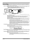
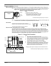
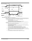
Single Phase Power Since the control rectifies all three input power phases, operation from a single phase power source is
not possible.
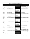
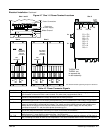
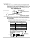
Table 4-3 Wire Size
Maximum
Armature
Current
Wire Size
Catalog
Number
Maximum
Output **
Cont. Peak
3f AC Input Armature
Field Power
Supply
Logic Power
Supply
BL1,BL2,BL3
HP kW
(Amps) (Amps)
AWG MM
2
AWG MM
2
AWG MM
2
AWG MM
2
AWG MM
2
BC29D7A35-CO7 20 15 35 53 8 8.37 8 8.37 14 2.08 12-22 3.31-0.326
BC29D7A70-CO7 40 30 70 105 4 21.2 3 26.7 14 2.08 14 2.08 6-18 13.3-0.823
BC29D7A110-CO7 60 50 110 165 1 42.4 1/0 53.5 14 2.08 14 2.08 6-18 13.3-0.823
BC29D7A165-CO7 100 75 165 248 3/0 85.0 4/0 107.0 14 2.08 14 2.08 6-18 13.3-0.823
BC29D7A243-CO1/CO2 150 120 243 365 300kcmil 152 350kcmil 177 14 2.08 14 2.08 6-18 13.3-0.823
BC29D7A380-CO1/CO2 200 150 380 570 700kcmil 355 750kcmil 380 8 8.37 14 2.08 6-18 13.3-0.823
BC29D7A500-CO1/CO2 300 225 500 750 1250kcmil 634 1500kcmil 760 8 8.37 14 2.08 6-18 13.3-0.823
BC29D7A725-CO1/CO2 400 327 725 1088 1″x3″ BB* 1″x3″ BB* 8 8.37 14 2.08 6-18 13.3-0.823
BC29D7A830-CO1/CO2 500 335 830 1245 1″x3″ BB* 1″x4″ BB* 8 8.37 14 2.08 6-18 13.3-0.823
BC29D7A1580-CO1/CO2 900 650 1580 2370 2″x4″ BB* 2″x4″ BB* 8 8.37 14 2.08 6-18 13.3-0.823
* BB is copper Bus Bar.
** Hp and kW are approximate at 500VDC Armature voltage.
Note: All wire sizes based on 75°C copper wire, 40°C ambient temperature, 4-6 conductors per conduit or raceway.
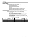
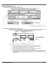
Table 4-4 Protection Devices
Fuse Rating
Catalog
Number
3f AC Line
(Ferraz–Shawmut)
Armature
(Ferraz–Shawmut)
Field Supply (A) Logic Supply (A)
BC29D7A35-CO7 A60Q40 A70QS50-14F 4 3
BC29D7A70-CO7 A50QS80-4R A70QS80 10 3
BC29D7A110-CO7 A50QS125-4R A70QS150 10 3
BC29D7A165-CO7 A50QS175-4R A70QS200 10 3
BC29D7A243-CO1/CO2 A50QS300-4R A70P350 10 3
BC29D7A380-CO1/CO2 A070URD32KI0400 A130URD73LI0450 30 3
BC29D7A500-CO1/CO2 A070URD32KI0630 A130URD73LI0700 30 3
BC29D7A725-CO1/CO2 A070URD32KI0800 A130URD73LI0900 30 3
BC29D7A830-CO1/CO2 A070URD32KI0900 14URD93TTF1250 30 3
BC29D7A1580-CO1/CO2 A070URD32KI0900 * 12.5URD94TDF2300M 30 3
* 6 fuses per drive.