


Appendix C
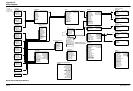
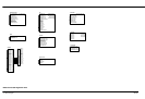
Block Diagram
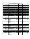
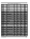
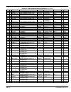
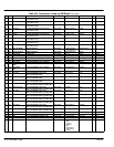
Block Diagram C-1MN792
SPT Sum 1 DEST [294]
SPT Sum [86]
Analog Input 1
Destination Tag [246]
[230] Calibration
[231] MAX Value
[232] MIN Value
ANIN 1 (A2) [50]
Analog Input 2
Output [493]
[233] Calibration
[234] MAX Value
[235] MIN Value
ANIN 2 (A3) [51]
Analog Input 3
Destination Tag [249]
[236] Calibration
[237] MAX Value
[238] MIN Value
ANIN 3 (A4) [52]
Digital Input 2
Destination Tag [105]
[106] Value True
[107] Value False
DIGIN 2 (C7) [72]
Analog Input 5
Destination Tag [247]
[242] Calibration
[243] MAX Value
[244] MIN Value
ANIN 5 (A6) [54]
Digital Input 1
Destination Tag [102]
[103] Value True
[104] Value False
DIGIN 1 (C6) [71]
Analog Input 4
Destination Tag [250]
[239] Calibration
[240] MAX Value
[238] MIN Value
ANIN 4 (A5) [53]
Digital Input 3
Destination Tag [108]
[109] Value True
[110] Value False
DIGIN 3 (C8) [73]
Current Loop
At Current Limit [42][15] Cur Limit/Scaler
[421] Main Cur Limit
[16] Prop Gain
[137] Discontinuous
[30] Additional Dem
[90] Bipolar Clamps
[136] Feed Forward
[17] Int Gain
IA Demand [66]
IA Feedback [65]
IA Feedback [538]
IF Feedback [539]
Autotune [18]
ILoop Suspend [46]
Master Bridge [527]
[201] Regen Mode
[301] Pos I Clamp
[48] Neg I Clamp
[119] I DMD Isolate
Setpoint Sum 1
[6] Ratio 1
[208] Ratio 0
[419] Divider 1
[420] Divider 0
[131] Deadband
[292] Sign 0
[8] Sign 1
[375] Limit
[423] Input 2
[100] Input 1
[309] Input 0
Jog/Slack
Operating Mode [212]
[219] Jog Speed 2
[253] Take Up 1
[254] Take Up 2
[218] Jog Speed 1
[225] Crawl Speed
[228] Mode
[355] Ramp Rate
5703
Destination Tag [135]
[134] Source Tag
[132] Setpt Ratio
[133] Setpt Sign
89
Raw Input [187]
Stop Rates
Speed Demand [89]
[27] Stop Time
[217] Stop Limit
[302] Contactor Delay
[26] Prog Stop Time
[216] Prog Stop Limit
[91] Prog Stop I LIM
[29] Stop Zero Speed
Program Stop [80]
Speed Loop
SPD Loop Output [549][14] SPD Prop Gain
[13] SPD Int Time
[202] Int Defeat
[289] Setpoint 1
[9] Sign 2 (A3)
[7] Ratio 2 (A3)
[47] Speed Fdbk Sel
[49] Encoder Sign
Speed Feedback [62]
Speed Setpoint [63]
UNFIL SPD Error [64]
Setpoint 2 (A3) [290]
[291] Setpoint 3
[41] Setpoint 4
[357] Max Demand
[358] Min Demand
Standstill
At Zero Setpoint [78][306] Source Tag
[11] Standstill Logic
[12] Zero Threshold
89
At Zero Speed [77]
At Standstill [79]
Alarms
Ready [125]
[19] Field Fail
[111] 5703 RCV Error
[28] Stall Trip
[92] Encoder Alarm
[540] REM Trip Inhibit
[541] REM Trip Delay
[81] Speed Fdbk Alarm
[305] Trip Reset
Healthy [122]
Health Word [115]
Health Store [116]
Remote Trip [542]
Stall Trip [112]
Last Alarm [528]
Field Control
Field Enable [169][170] Field Enable
[209] FLD CTRL Mode IS
[210] FLD Volts Ratio
[172] Int Gain
[174] FLD Weak Enable
[175] EMF Lead
[173] Prop Gain
[171] Setpoint
Field Demand [183]
Field Firing Angle [184]
[176] EMF Lag
[177] EMF Gain
[179] MIN Field Curent
[192] BEMF FBK Lag
[185] FLD Quench Delay
[186] FLD Quench Mode
[191] BEMF FBK Lead
[178] MAX Volts
Calibration
Terminal Volts [57][20] Armature V Cal
[21] IR Compensation
[22] Encoder RPM
[10] Zero SPD Offset
[25] Armature I (A9)
[180] SPD FBK Alarm Level
[23] Analog Tach Cal
[24] Encoder Lines
Unfil Tach Input [58]
Encoder [59]
[263] Stall Threshold
[224] Stall Trip Delay
[188] Overspeed Level
[275] Position Divider
[521] NOM Motor Volts
[523] Armature Current
[267] Position Count
[182] Field I Cal
Back EMF [60]
Field FBK [181]
[524] Field Current
Analog Output 1
ANOUT 1 (A7) [55][251] Input
[245] 10V CAL
[464] Offset
62
[362] Modulus
Analog Output 2
ANOUT 2 (A8) [56][252] Input
[248] 10V CAL
[465] Offset
63
[363] Modulus
Digital Output 1 (B5)
DIGOUT 1 (B5) [74][97] Input
[359] Inverted
[195] Threshold
77
[43] Modulus
Digital Output 2 (B6)
DIGOUT 2 (B6) [75][98] Input
[360] Inverted
[196] Threshold
122
[44] Modulus
Digital Output 3 (B7)
DIGOUT 3 (B7) [76][99] Input
[361] Inverted
[197] Threshold
125
[45] Modulus
Aux I/O
Start (C3) [68]
[161] AUX Start
[227] AUX Jog
[168] AUX Enable
[94] AUX DIGOUT 1
[95] AUX DIGOUT 2
[96] AUX DIGOUT 3
[128] ANOUT1
Seq Status [537]
[129] ANOUT2
[536] REM Sequence
[535] REM SEQ Enable
[496] Jog/Slack
[497] Enable
[547] SPD FBK Filter
496
100
228
309
301
48
119
5
0-20mA Input
For 4-20mA,
Set Min Value =25%
Max Value = 125%
Analog Input 2 = -25%
Ramps
Ramp Output [85]
[2] Ramp Accel Time
[3] Ramp Decel Time
[4] Constant Accel
[266] % S-Ramp
[286] Ramping Thresh
[287] Auto Reset
[620] Ramp Invert
[118] Ramp Hold
Ramping [113]
[288] External Reset
[422] Reset Value
[126] MIN Speed
Ramp O/P DEST [293]
289
Diagnostics
Speed Feedback [207]
Speed Error [297]
Current Demand [299]
Current Feedback [298]
POS I Clamp [87]
NEG I Clamp [88]
Actual POS I Limit [67]
Actual NEG I Limit [61]
Drive Start [82]
Drive Enable [84]
Field I Feedback [300]
TACH Input (B2) [308]
Encoder [206]
Configure Drive
[521] NOM Motor Volts
[523] Armature Current
[524] Field Current
[209] Field Control Mode
[210] Field Volts Ratio
[47] Speed Feedback Select
[22] Encoder RPM
[24] Encoder Lines
[49] Encoder Sign
41
Enable & Jog/Slack Inputs
Terminal Strip Jog/Slack Settings
Optional Drive Status Outputs (Read Only)
Use Minimum field current to set
Maximum Speed in Field Weakening
±10VDC Input w/o Ramp
±10VDC Input with Ramp
Optional Reverse I Limit
External I Limit
Jog/Slack
Speed/Torque Select
Jog/Slack Mode
Unfiltered Speed Feedback
Unfiltered Speed Command
At Zero Speed
Drive Ready
Drive Healthy
Baldor Series 29D Digital DC Drive
C4
Destination Tag [494]
DIGIN E (C4) [69]
C5
Destination Tag [495]
DIGIN R (C5) [70]
497
620
Reverse
Enable
[5] Ramp Input
Scaled Input [189]
[595] Preset Torque
[604] Preset T Scale
Up To Field [618]
[617] FLD I Threshold
Drive Running [376]
Contactor Closed [83]