


Receiving & Installation 4-3MN792
Cover Removal Continued
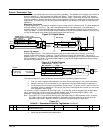
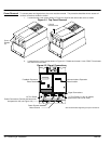
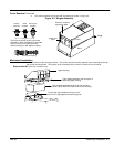
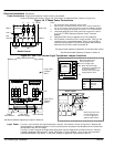
3. The control and base are hinged and are opened as shown in Figure 4-3.
Figure 4-3 Hinged Assembly
Raise the control to
expose the base
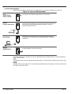
The knock–out panel is part of the base
assembly to allow connections to be made.
Use the correct size rubber grommet,
conduit coupling or 360 degree coupling.
Hinge
Base
Control
Knock–out
panel
Rubber
Grommet
Metal
Coupling
360 Degree
Coupling
360 Degree Coupling
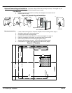
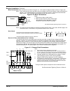
Mechanical Installation
Mount the control to the mounting surface. The control must be securely fastened to the mounting surface by
the control mounting holes. The location of the mounting holes is shown in Section 9 of this manual.
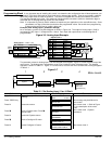
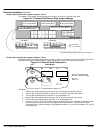
External Vent Kit (Size 4 & 5 controls only)
Upper Housing
Foam gasket stretches over duct prior to
attaching upper housing.
Duct slides down between duct clip and mounting
panel and fits within the sides of the control housing.
Fit duct clip under fasteners at top of drive.
Be sure it is tight against the mounting panel.