


Getting Started 3-3MN792
Source / Destination Tags
The control is very flexible because of the programming capability. The software block diagram of the control is
shown in Appendix C. Each logic block has inputs and outputs. These I/O points are called “Tags” because
they have a tag number associated with it and shown in brackets “[tag]” . Some tags are read only values and
some are read/write. Besides setting the value of each parameter, its source or destination connections can be
programmed. This means you can connect inputs and outputs of logic blocks as you desire to implement your
application.
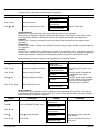
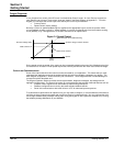
Destination Tag example
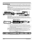
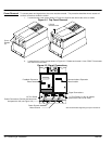
Consider Digital Input 1. The external connection (input) is made at the C connector pin 6. The block diagram of
this input is shown in Figure 3-3. Tag [102] is the destination tag for the output signal. The destination is
presently set to 90. This connects the output of Digital Input 1 to the Bipolar Clamps [90] input of the Current
Loop Logic Block. The value of [102] Digital output is determined by the switch position, either the value of [103]
or [104] will be applied to the output as the input changes from false to true.
Figure 3-3 Digital Inputs
[102] Destination Tag 90
[104] Value for False 0.00%
Tag Parameter Setting
Digital
Input 1
[102]
C6
Digital Input 1 – DIGIN 1 (C6)
[103] Value for True 0.01%
[71]
Diagnostic
connection
[48] NEG I Clamp Analog IN 4
[90] Bipolar Clamps Digital IN 1
[88] NEG I Clamp
-1
[87] POS I Clamp
Current Loop
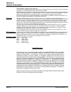
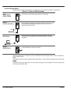
Source Tag example
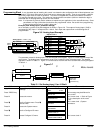
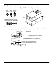
Consider Digital Output 1. The external connection (output) is made at the B connector pin 5. The block
diagram of this input is shown in Figure 3-4. Tag [97] is the source tag for the input signal. The source is
presently set to 77. This means that Digital output 1 receives its input signal from [77] At Zero Speed parameter
from the Standstill Logic Block. To connect Digital Output 1 to the At Zero Setpoint parameter, simply change
[97] Source Tag value from 77 to 78.
Figure 3-4 Digital Outputs
Tag Parameter
[195] Threshold (>)
0.00%
[359] Inverted False
Setting
[43] Modulus True
Digital
Output 1
[97] Source Tag 77
ABS
B5
Standstill
At Zero Setpoint [78][306] Source Tag
[11] Standstill Logic
[12] Zero Threshold
At Zero Speed [77]
At Standstill [79]
Digital Output 1 – DIOUT 1 (B5)
From these examples, it is easy to see that several things are required to program the control.
1. First, you must understand the application and know how to implement it in the control parameters.
2. Second, layout all of the connections for your application using the block diagrams in Appendix C.
3. Third, program the connections and parameter preset values. To do this you will need to refer to the
Parameter Values in Appendix B. This will tell you where in the keypad menu system you can locate
each parameter value or [tag].
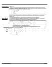
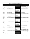
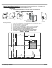
For example, find [97] in Appendix B, (see Figure 3-5). To locate [97] using the keypad, begin at the System
menu, select Configure I/O menu, then select Digital Outputs menu, finally select Digital Output 1 (B5)
parameter. Change the value of that parameter to the desired value.
Note: Tag number “[97]” is not shown at the keypad for the Digital Output 1 (B5) parameter value. To display
the [TAG] number of the parameter, display the parameter value then press the “M” key to show the
parameters tag number. Appendix B and C are the key to programming your application.
Figure 3-5
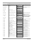
Table B-1 Parameters Listed by Tag Number
Continued
Tag R/W Name Keypad Menu WB Block Range Factory Setting MN Notes
97 RW Source Tag SYSTEM::CONFIGURE I/O::DIGITAL
OUTPUTS::DIGOUT 1 (B5)
Digout 1 (B5) 0 to 549 77 cp 2, 3
4. Select the next parameter and repeat step 3.