


4-18 Receiving & Installation MN792
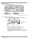
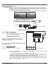
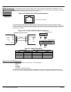
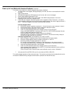
RS232 Connections The keypad connector shown in Figure 4-25 is used for RS232 communications. Workbench D is the
block programming software for Windows PCs. It has a graphical user interface and drawing tools to allow you
to create block programming diagrams quickly and easily.
Figure 4-25 System Port (P3) Keypad Connector
12 34
View into the connector.
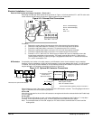
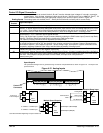
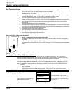
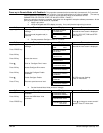
A null modem cable (also called a modem eliminator cable) must be used to connect the control and the
computer COM port. This will ensure that the transmit and receive lines are properly connected. Either a 9 pin
or a 25 pin connector can be used at the computer, Figure 4-26. Maximum recommended length for RS232
cable is 10 ft. (3 meter).
Figure 4-26 9 & 25 Pin RS-232 Cable Connections
25 Pin Connector
9 Pin Connector
Pin Signal
3 RXD
2 TXD
7 GND
Pin Signal
2 RXD
3 TXD
5 GND
Null Modem Cable Connections
Control
(DCE)
Computer
COM
Port
(DTE)
RXD
TXD
GND
RXD
TXD
GND
Chassis
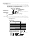
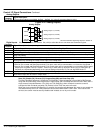
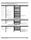
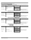
Table 4-8 Cable Connections
P3 Connector DB Connector Type and Pin Number
Pin Signal Name DB9 DB25
1 GND/0VDC 5 7
2 24VDC
3 RXD 2 3
4 TXD 3 2
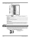
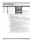
System Port (P3) Configuration
The factory port settings are normally fine. These settings are:
9600 Baud
8 Bits
1 Stop Bit
No Parity
XON/XOFF Handshaking (fixed)
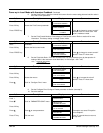
If the port settings must be changed, attach a keypad to the control and change the settings under the P3
SETUP menu. Refer to Keypad Operation for additional information to make these parameter value changes.
1 SERIAL LINKS
2 SYSTEM PORT P3
3 P3 SETUP
MODE
P3 BAUD RATE