


Programming 6-23MN792
Digital Inputs Continued
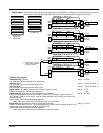
Digital input 1 now sends a 0 when the input signal is true and 1 when it is false.
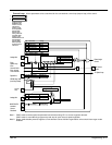
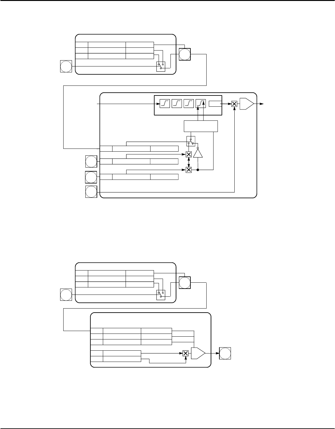
ANALOG I/P 5
-
+
A5
A6
Analog IN 4
From
Speed Loop
[66]
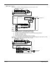
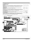
[48] NEG I Clamp Analog IN 4
[90] Bipolar Clamps Digital IN 1
[301] POS I Clamp Analog IN 5
-1
PI
[65]
Armature Current
Feedback
Phase Angle Control
Current Limit
Switch
Current Loop
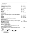
[102] Destination Tag 90
[104] Value for False 0.01%
Tag Parameter
Setting
Digital
Input 1
[102]
C6
Digital Input 1 – DIGIN 1 (C6)
[103] Value for True 0.00%
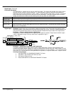
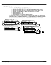
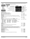
Example 3 – Use Digital Input 1 to set Speed Loop PROP Gain
1. Set CONFIGURE I/O::CONFIGURE ENABLE to ENABLE.
2. Set DIGIN 1 (C6)::DESTINATION TAG to 14 (the speed loop prop gain parameter).
3. Set VALUE FOR TRUE to 10.00.
4. Set VALUE FOR FALSE to 30.00.
5. Reset CONFIGURE I/O::CONFIGURE ENABLE to DISABLE.
Digital input 1 now sets SPEED LOOP::PROP. GAIN to two values depending upon its state. When it is HIGH,
PROP. GAIN is at 10.00 and when LOW, PROP. GAIN is at 30.00.
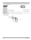
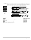
0.500 Seconds
Speed Loop
[102] Destination Tag 14
[104] Value for False 30.00%
Tag Parameter
Setting
Digital
Input 1
[102]
C6
Digital Input 1 – DIGIN 1 (C6)
[103] Value for True 10.00%
-
+
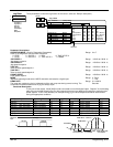
PI
To Current Loop I DMD
Isolate switch input
[14] PROP Gain 10.00
[13] INT Time Constant
Tag Parameter Setting
[202] INT Defeat Off
[89] Speed Demand
[207] Speed Feedback
[356]