


3-4 Getting Started MN792
Programming Block A very important step to installing this control is to determine the configuration that will best implement your
application. Each input and output of each block has an assigned tag number. Tags are connected in software
much like jumper wires are used in hardware. The control is shipped with a factory set software connection.
This may be changed at any time. The method of changing these connections (source or destination tags) is
described later in the programming Section 6 of this manual.
Note: It is important to correctly set the software to implement your application in the most efficient way. Some
parameters are Tags (connections) and others are programmed values. Be careful when programming
to be sure the correct input or output is being set.
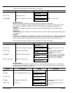
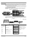
Example (View Analog Input 1 parameter settings)
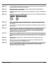
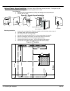
As an example, a portion of the block diagram is shown in Figure 3-6. The output of Analog Input 1 [246] is
connected to [100] “Input 1” of Setpoint Sum 1 block. Each input and output shown on these diagrams is
programmable.
Figure 3-6 Analog Input Example
[231] Max Value +100.00%
[230] Calibration 1.0000
Tag Parameter
Factory Setting
[232] Min Value -100.00%
[246] Destination Tag 100
Analog
Input 1
Analog Input 1 – ANIN 1 (A2)
[246]
A2
Setpoint Sum 1
[292] Sign 0 Positive
Tag Parameter
Factory Setting
A/B
[208] Ratio 0 1.0000
[309] Input 0 0.00%
[420] Divider 0 1.0000
[423] Input 2 0.00%
+
+
+
[6] Ratio 1 1.0000
[100] Input 1 0.00%
[131] Deadband Width 0.00%
A/B
+
-
+
-
[419] Divider 1 1.0000
[8] Sign 1 Positive
[375] Limit 105.00%
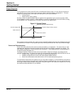
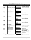
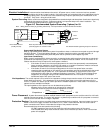
The parameter values for Analog Input 1 can be changed at the keypad. Figure 3-7 shows a partial map of the
menu levels. The Analog Input 1 parameters are at Level 4 under the Level 3 Analog Inputs. The keypad
operation is shown in Table 3-1. Figure 3-7 can be used to visualize the menu structure that is being navigated
in Table 3-1.
Figure 3-7
1234
Diagnostics
Menu Levels
System
Software
Configure I/O
Analog Inputs ANIN1 (A2)
Configure Enable
Calibration
MAX Value
MIN Value
Destination Tag
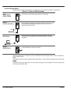
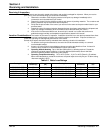
Table 3-1 Set Analog Input 1 for 4–20mA
Action Description Display Comments
Apply Power Keypad Display shows this opening
message.
FORWARD
REF: 0.00%
Press “PROG” key
BALDOR DC DRIVE
DC 4Q 35A
This message may be different for
each control.
Press M Access the menus.
MENU LEVEL
DIAGNOSTICS
This is menu level 1. Refer to Figure
3-7 for a description of the menu
levels.
Press B Scroll to System menu. Press B
several times.
MENU LEVEL
SYSTEM
This is menu level 1, System
parameters.
Press M Access the System menus.
SYSTEM
SOFTWARE
Press B
Scroll to Configure I/O menu.
SYSTEM
CONFIGURE I/O
Press M Access Configure I/O menu.
CONFIGURE I/O
CONFIGURE ENABLE
This is menu level 2.