


Appendix B
Parameter Table
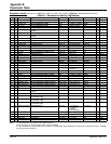
Parameter Table B-1MN792
Parameter Values (Version 5.13) RW: RO = Read Only, RW = Read / Write. WB Block = WorkbenchD Block name.
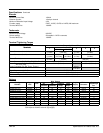
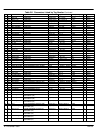
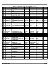
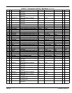
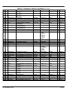
Table B-1 Parameters Listed by Tag Number
Tag R/W Name Keypad Menu WB Block Range Factory Setting MN Notes
2 RW Ramp Accel Time SETUP PARAMETERS::RAMPS Ramps 0.1 to 600.0 Secs 10.0 Secs a2
3 RW Ramp Decel Time SETUP PARAMETERS::RAMPS Ramps 0.1 to 600.0 Secs 10.0 Secs a3
4 RW Constant Accel SETUP PARAMETERS::RAMPS Ramps 0 : Disabled 1 : Enabled Enabled a4
5 RW Ramp Input SETUP PARAMETERS::RAMPS Ramps -105.00 to 105.00 % 0.00% a5
6 RW Ratio 1 SETUP PARAMETERS::SETPOINT SUM 1 Setpoint Sum 1 -3.0000 to 3.0000 1.0000 a6
7 RW Ratio 2 (A3) SETUP PARAMETERS::SPEED LOOP::SETĆ
POINTS
Speed Loop -3.0000 to 3.0000 .0000 a7
8 RW Sign 1 SETUP PARAMETERS::SETPOINT SUM 1 Setpoint Sum 1 0 : Negative 1 : Positive Positive a8
9 RW Sign 2 (A3) SETUP PARAMETERS::SPEED LOOP::SETĆ
POINTS
Speed Loop 0 : Negative 1 : Positive Positive a9
10 RW Zero SPD. Offset SETUP PARAMETERS::CALIBRATION Calibration -5.00 to 5.00 % 0.00% aa
11 RW Standstill Logic SETUP PARAMETERS::STANDSTILL Standstill 0 : Disabled 1 : Enabled Disabled ab
12 RW Zero Threshold SETUP PARAMETERS::STANDSTILL Standstill 0.00 to 100.00 % 2.00% ac
13 RW SPD.INT.TIME CONFIGURE DRIVE Speed Loop 0.001 to 30.000 Secs 0.500 Secs ad
14 RW SPD.PROP.GAIN CONFIGURE DRIVE Speed Loop 0.00 to 200.00 10 ae
15 RW CUR.LIMIT/SCALER CONFIGURE DRIVE Current Loop 0.00 to 200.00 % 90.00% af
16 RW PROP. GAIN SETUP PARAMETERS::CURRENT LOOP Current Loop 0.00 to 200.00 45.00 ag
17 RW INT. GAIN SETUP PARAMETERS::CURRENT LOOP Current Loop 0.00 to 200.00 3.50 ah
18 RO Autotune CONFIGURE DRIVE Current Loop 0 : Off 1 : On Off ai Output, 1
19 RW Field Fail SETUP PARAMETERS::INHIBIT ALARMS Alarms 0 : Enabled 1 : Inhibited Enabled aj
20 RW Armature V CAL. SETUP PARAMETERS::CALIBRATION Calibration 0.9800 to 1.1000 1.0000 ak
21 RW IR Compensation SETUP PARAMETERS::CALIBRATION Calibration 0.00 to 100.00 % 0.00% al
22 RW Encoder RPM CONFIGURE DRIVE Calibration 0 to 6000 RPM 1750 RPM am
23 RW Analog TACH CAL SETUP PARAMETERS::CALIBRATION Calibration 0.9800 to 1.1000 1.0000 an
24 RW Encoder Lines CONFIGURE DRIVE Calibration 10 to 5000 1024 ao 2
25 RW Armature I (A9) SETUP PARAMETERS::CALIBRATION Calibration 0 : UNIPOLAR
1 : BIPOLAR
Bipolar ap
26 RW PROG Stop Time SETUP PARAMETERS::STOP RATES Stop Rates 0.1 to 600.0 Secs 0.1 Secs aq
27 RW Stop Time SETUP PARAMETERS::STOP RATES Stop Rates 0.1 to 600.0 Secs 10.0 Secs ar
28 RW Stall Trip SETUP PARAMETERS::INHIBIT ALARMS Alarms 0 : Enabled 1 : Inhibited Inhibited as
29 RW Stop Zero Speed SETUP PARAMETERS::STOP RATES Stop Rates 0.00 to 100.00 % 2.00% at
30 RW Additional DEM SETUP PARAMETERS::CURRENT LOOP Current Loop -200.00 to 200.00 % 0.00% au
31 RW SPD BRK2 (HIGH) SETUP PARAMETERS::CURRENT PROFILE Current Profile 0.00 to 100.00 % (h) 100.00% av 2
32 RW SPD BRK1 (LOW) SETUP PARAMETERS::CURRENT PROFILE Current Profile 0.00 to 100.00 % (h) 100.00% aw 2
33 RW IMAX BRK2(SPD2) SETUP PARAMETERS::CURRENT PROFILE Current Profile 0.00 to 200.00 % (h) 200.00% ax 2
37 RW FULL MENUS MENUS Menus 0 : Disabled 1 : Enabled Enabled b1
39 RW Configure Enable CONFIGURE DRIVE Unallocated 0 : Disabled 1 : Enabled Disabled b3 2
41 RW Setpoint 4 SETUP PARAMETERS::SPEED LOOP::SETĆ
POINTS
Speed Loop -105.00 to 105.00 % 0.00% b5
42 RO At Current Limit DIAGNOSTICS Current Loop 0 : False 1 : True False b6 Output
43 RW Modulus SYSTEM::CONFIGURE I/O::DIGITAL OUTĆ
PUTS::DIGOUT 1 (B5)
Digout 1 (B5) 0 : False 1 : True TRUE b7
44 RW Modulus SYSTEM::CONFIGURE I/O::DIGITAL OUTĆ
PUTS::DIGOUT 2 (B6)
Digout 2 (B6) 0 : False 1 : True TRUE b8
45 RW Modulus SYSTEM::CONFIGURE I/O::DIGITAL OUTĆ
PUTS::DIGOUT 3 (B7)
Digout 3 (B7) 0 : False 1 : True TRUE b9
47 RW SPEED FBK SELECT CONFIGURE DRIVE Speed Loop 0 : Arm Volts Fbk
1 : Analog Tach
2 : Encoder
3 : Encoder/Analog
Arm Volts Fbk bb
2
48 RW NEG. I CLAMP SETUP PARAMETERS::CURRENT LOOP Current Loop -100.00 to 100.00 % 0.00% bc
49 RW ENCODER SIGN CONFIGURE DRIVE Speed Loop 0 : Negative 1 : Positive Positive bd 2
50 RO ANIN 1 (A2) DIAGNOSTICS Analog Input 1 xxx.xx VOLTS 0.00V be Output
51 RO ANIN 2 (A3) DIAGNOSTICS Analog Input 2 xxx.xx VOLTS 0.00V bf Output
52 RO ANIN 3 (A4) DIAGNOSTICS Analog Input 3 xxx.xx VOLTS 0.00V bg Output
Notes: 1. This parameter is not saved in non–volitile memory.
2. This parameter can only be written when control is stopped.
3. This parameter can only be written when contol is in configuration mode (stopped & Configure Drive::Configure Enable = Enabled).
4. This parameter is reserved.