


Programming 6-19MN792
Diagnostics Continued
Parameter Descriptions
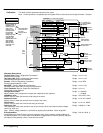
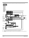
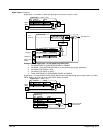
Inverse Time Output (shown in Current Loop block)
Inverse time clamp output level.
Range: xxx.xx %
At Current Limit (shown in Current Loop block)
Current demand is being restrained by the overall current limit.
Range: 0 : False
1 : True
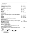
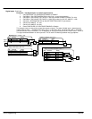
At Zero Speed (shown in Standstill block)
At zero speed feedback.
Range: 0 : False
1 : True
At Zero Setpoint (shown in Standstill block)
At zero speed demand.
Range: 0 : False
1 : True
At Standstill (shown in Standstill block)
At zero speed and at zero setpoint.
Range: 0 : False
1 : True
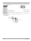
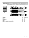
Ramping (shown in Ramps block)
If the difference between the Ramp Input and The Ramp Output is greater than the Ramp
Threshold, then Ramping is true.
Range: 0 : False
1 : True
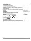
Program Stop (shown in Stop Rates block)
State of Program Stop (Terminal B8). When B8 is at 24V, then Program Stop is false and the
Program Stop front panel LED is also on.
Range: 0 : False
1 : True
Coast Stop (Diagnostics only)
State of Coast Stop (Terminal B9). When B9 is at 24V, then Coast Stop is False.
Range: 0 : False
1 : True
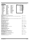
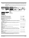
Operating Mode (shown in Jog/Slack block)
Sets the drive mode to Run, Jog 1....stop, etc.
0 : Stop
1 : Stop
2 : Jog Sp. 1
3 : Jog Sp. 2
4 : Run
5 : Take Up Sp. 1
6 : Take Up Sp. 2
7 : Crawl
Range: 0 to 7
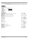
Field Enabled (shown in Field Control block)
Drive Field Loop Is Enabled/Quenched.
Range: 0 : Disabled
1 : Enabled
Field Demand (shown in Field Control block)
The meaning of field demand depends upon which mode of field control is in force; in current control
field demand is the current setpoint to the field loop, in voltage mode field demand is the voltage
ratio to the field controller.
Range: xxx.xx %
FIELD I FBK AMPS (shown in Current Loop block, IF Feedback)
Scaled and filtered field current feedback in Amps.
Range: xxx.xx %
Raw Field FBK
Scaled field current.
Range: xxx.xx %
FLD. Firing Angle (shown in Field Control block)
Field firing angle in degrees: 155 degrees is the value for back stop (min field) and 5 degrees is the
value for front stop (max field).
Range: xxx.xx DEG
ANIN 1 (A2) (shown in Analog Inputs block)
Speed setpoint no. 1.
Range: xxx.xx Volts
ANIN 2 (A3) (shown in Analog Inputs block)
Speed setpoint no. 2/current demand.
Range: xxx.xx Volts
ANIN 3 (A4) (shown in Analog Inputs block)
Speed setpoint no. 3 (ramped).
Range: xxx.xx Volts
ANIN 4 (A5) (shown in Analog Inputs block)
Negative current clamp; this is only active if bipolar clamps are enabled
(C6 = ON)
Range: xxx.xx Volts
ANIN 5 (A6) (shown in Analog Inputs block)
Main current limit or positive current clamp if C6 = on.
Range: xxx.xx Volts
ANOUT 1 (A7) (shown in Analog Outputs block)
Scaled speed feedback.
Range: xxx.xx Volts
ANOUT 2 (A8) (shown in Analog Outputs block)
Total speed setpoint.
Range: xxx.xx Volts
Start (C3) (shown in AUX I/O block)
Start/Run terminal.
Range: 0 : Off
1 : On