


6-40 Programming MN792
Speed Loop Continued
Parameter Descriptions
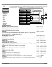
Speed Loop Output SPD Loop Output (Read in Diagnostics Parameters)
Output from Speed Loop PI.
Range: xxx.xx %
Speed Feedback (Read in Diagnostics Parameters)
The speed feedback value from the source chosen by SPEED FBK SEL.
Range: xxx.xx %
Speed Setpoint (Read in Diagnostics Parameters)
Speed loop total setpoint including the ramp output before the ramp–to–zero function.
Range: xxx.xx %
Speed Error (Read in Diagnostics Parameters)
Speed loop error.
Range: xxx.xx %
Speed PROP. Gain (Can be set in Speed Loop or Configure Drive.)
Speed loop Pi proportional gain adjustment.
Range: 0.00 to 200.00
Speed INT. Time (Can be set in Speed Loop or Configure Drive.)
Speed loop PI integral gain adjustment.
Range: 0.001 to 30.000
Seconds
INT. DEFEAT
Inhibits the integral part of the speed loop PI to give proportional control only.
Range: 0 : Off
1 : On
Encoder Sign (Can be set in Speed Loop or Configure Drive.)
Since the encoder feedback cannot be reversed electrically, the signal polarity can be reversed by
the control software.
Range: 0 : Negative
1 : Positive
Speed FBK Select (Can be set in Speed Loop or Configure Drive.)
Four options are available:
0 : ARM Volts FBK
1 : Analog TACH
2 : Encoder
3 : Encoder/Analog
Range: 0 to 3
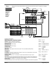
Setpoint 1
Speed Setpoint 1.
Range: –105.00 to 105.00 %
Sign 2 (A3)
Speed Setpoint 2 Sign.
Range: 0 : Negative
1 : Positive
Parameter Descriptions
Ratio 2 (A3)
Speed Setpoint 2 Ratio.
Range: –3.0000 to 3.0000
Setpoint 2 (A3) This is a fixed (non–configurable) input.
This setpoint is scanned synchronously with the current loop .
Range: xxx.xx %
Setpoint 3
Speed Setpoint 3.
Range: –105.00 to 105.00 %
Setpoint 4
Speed Setpoint 4.
Range: –105.00 to 105.00 %
MAX Demand
Sets the maximum input to the speed loop. It is clamped at 105% to allow for overshoot in the
external loops.
Range: 0.00 to 105.00 %
MIN Demand
Sets the minimum input to the speed loop.
Range: –105.00 to 105.00 %
I Gain in Ramp Range:
POS Loop P Gain Range:
Zero SPD Level Range:
Zero IAD Level Range:
Functional Description
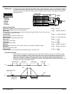
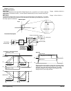
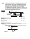
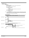
Speed Loop PI Output – The PI output is available for connection using tag no. 356. This point is before the I Limit clamps
and the summing of the additional current demand. This tag is not visible at the keypad.
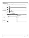
Speed Loop PI with Current Demand Isolate – The speed loop output is still valid (active) with the I DMD. Isolate parameter
enabled.
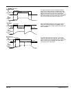
1. The speed loop is reset by unquenching the speed loop/current loop.
2. I DMD. ISOLATE is overridden by Program Stop (B8) or Normal Stop (C3).
3. The speed loop PI holds the integral term as soon as the PI output reaches current limit. This is true even in Current
Demand Isolate mode where it may interfere depending on the way the speed PI is used. At the present time. this feature
cannot be suppressed.
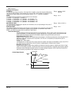
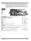
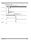
105% Speed Demands – The speed demand clamping allows the speed setpoint to reach 105%. This applies only to the
final summing junction immediately before the speed loop and also to the Setpoint Sum 1 output. Individual speed setpoints
are still clamped to 100%.