


6-16 Programming MN792
Current Loop Continued
Parameter Descriptions
At Current Limit (Read in Diagnostics Parameters)
True indicates that current demand equals or exceeds maximum current limit.
Range: 0 : False
1 : True
IA Demand (Read in Diagnostics Parameters)
(IaDmd Unfiltered)
Range: xxx.xx % (h)
IA Feedback (Read in Diagnostics Parameters)
(IaFbk Unfiltered)
Range: xxx.xx % (h)
Current FBK.AMPS (Read in Diagnostics Parameters)
Scaled and filtered armature current in Amps.
Range: xxx.xx AMPS
IF Feedback (Read in Diagnostics Parameters)
(Field I FBK.AMPS)
Range: xxx.xx AMPS
Autotune
This is the autotune function trigger input.
Range: 0 : Off
1 : On
ILOOP Suspend
Reserved parameter.
Range: 0 : False
1 : True
Master Bridge
A diagnostic indicating currently active bridge; master = ON, slave = OFF.
Range: 0 : Off
1 : On
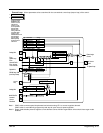
Main CURR. Limit
Main current limit parameter which is independent of current limit scaler and in series with the other
three current limit blocks.
Range: 0.00 to 200.00 %
PROP Gain
Proportional gain control for armature current pi loop. this parameter is set during the autotune
function.
Range: 0.00 to 200.00
INT Gain
Integral gain control for armature current PI loop. This parameter is set during the autotune function.
Range: 0.00 to 200.00
Feed Forward
Set by Autotune but not used by the factory set I–Loop mode
Range: 0.10 to 50.00
Discontinuous
Discontinuous–to–continuous mean armature current boundary level. This parameter is set during
the autotune function and affects the performance of the adaptive algorithm.
Range: 0.00 to 200.00 %
Additional DEM
Additional current demand input
Range: –200.00 to 200.00 %
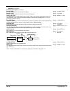
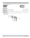
Bipolar Clamps
Select input for bipolar (asymmetric) or unipolar (symmetric) current clamps for the 4 quadrants of
operation. Factory setting of DISABLED means UNIPOLAR clamps selected.
Range: 0 : Disabled
1 : Enabled
Regen Mode – Series 30 controls only
Set mode for regenerative (4–quadrant) or non–regenerative (2–quadrant) operation. Do not
changed while the control is in operation.
Range: 0 : 2Q (Non–regen)
1 : 4Q (Regen)
POS. I Clamp
Positive current clamp in Bipolar Clamp mode.
Range: –100.00 to 100.00 %
NEG. I Clamp
Negative current clamp in Bipolar Clamp mode.
Note: Note bipolar current clamps in bipolar mode can cross over onto the same quadrant as
long as the POS. I Clamp is always algebraically greater than the NEG. I Clamp.
Range: –100.00 to 100.00 %
CUR. LIMIT/SCALER
Current limit scaler. It scales bipolar/unipolar clamps.
Range: 0 to 200.00 %
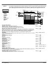
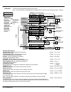
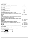
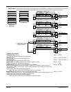
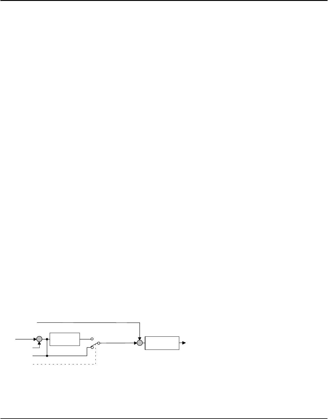
I DMD Isolate
Speed loop bypass: the current demand input is ANIN2 (A3). The following diagram shows that I
DMD Isolate selects the controlling loop.
Range: 0 : Disabled
1 : Enabled
SPEED LOOP PI
CURRENT LOOP PI
Speed Demand
Speed Feedback
Analog I/P2 (A3)
Digital I/P3 (C8)
I DMD ISOLATE
Current Demand
Current Feedback
Motor
shown ENABLED
+
-
+
-