


4-16 Receiving & Installation MN792
Control I/O Signal Connections Continued
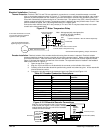
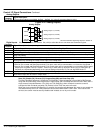
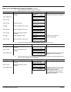
Analog Outputs
Connector
Terminal
Signal Description
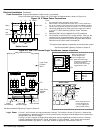
A7, A8, A9 Three analog outputs are available, AnOut1 – AnOut3. A1 is the 0V common reference point.
Figure 4-22 Analog Outputs
See Recommended Tightening Torques in Section 9.
Analog Outputs
A7
Control
A10V
A8
Analog Output 1 (±10VDC)
AnOut1
AnOut2
Analog Output 2 (±10VDC)
A9Arm I Fbk
Analog Output 3 (±10VDC)
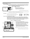
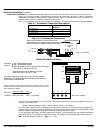
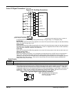
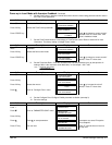
Digital Inputs C4 (Enable) must be connected to C9 (+24V) to allow the drive to run when start command is given.
Connector
Terminal
Signal Description (factory settings)
B8 Program Stop. When opened runs a decel rate set by Stop Rates, Prog Stop Time.
B9 Coast Stop. When opened disables the drive output.
C2 External Trip. When opened disables the drive output and creates an External Trip Fault.
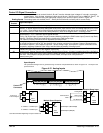
C3 Start/Stop. Closed initiates a Start/Run forward sequence. When opened commands Stop and decels at Stop Rates,
Stop Time setting.
C4 Enable. Closed enables the drive and allows output to the motor.
C5 Reverse. Closed changes the slope of the speed command signal from Analog Input 1 and Analog Input 2.
Accomplished by activating the “Ramp Invert” input of the Ramps block.
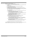
C6 Jog / Slack.
If terminal C4 is closed and Start/Stop terminal C3 is open, motor will be commanded to run forward at Jog Speed 1.
If terminal C4 is closed and Start/Stop terminal C3 is closed, motor will be commanded to run forward at active speed
setpoint plus Jog/Slack Take Up 1 speed. Various Jog or Slack take–up functions Various Jog or Slack take–up
functions are commanded depending on the various settings of terminals C3, C4 and Jog/Slack Mode C7.
C7 Jog/Slack Mode. See Jog/Slack description in Section 6 for description of modes.
C8 Speed/Torque Select. Open selects speed (velocity) mode. Closed selects current (torque) mode.
Accel/Decel ramps are not used in Torque mode.
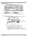
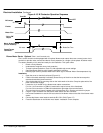
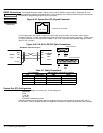
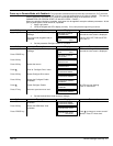
Start (C3), Enable (C4), Reverse (C5), Program Stop (B8) and Coast Stop (C9).
The basic Run/Start sequence is initiated by C3 (Start/Run). Other safeguards are provided by B8 (Program
Stop) and B9 (Coast Stop). Assuming that the Program Stop and Coast Stop terminals are held TRUE, then a
single contact connected between C9 (+24V) and C3 (Start/Run) when closed will cause the control to
energize the Main Contactor and when C5 (Enable) is also TRUE the motor will rotate.
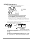
When the single contact to C3 (Start/Run) is opened, the controller will decelerate the motor to zero speed at a
rate determined by the STOP TIME parameter value and the MAIN CURR. LIMIT value. If the load is to be
serviced, the control must be securely disabled and isolated, do not rely on this mode.