


Programming 6-21MN792
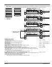
Digital Inputs
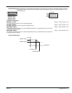
Allows control of the digital operating parameters of the software. The digital input can be configured to point to
a destination location and to set that destination true or false depending upon programmable values.
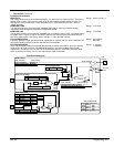
1 SYSTEM
2 CONFIGURE I/O
3 DIGITAL INPUTS
4 DIGIN 1 (C6)
4 DIGIN 2 (C7)
4 DIGIN 3 (C8)
Destination Tag
Value for True
Value for False
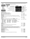
1 SYSTEM
2 CONFIGURE I/O
3 DIGITAL INPUTS
4 DIGITAL INPUT C4
4 DIGITAL INPUT C5
Destination Tag
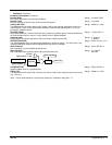
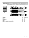
[102] Destination Tag 90
[104] Value for False 0.00%
Tag Parameter
Setting
Digital
Input 1
[102]
C6
Digital Input 1 – DIGIN 1 (C6)
[103] Value for True 0.01%
[105] Destination Tag 118
[107] Value for False 0.00%
Tag Parameter
Setting
Digital
Input 2
C7
Digital Input 2 – DIGIN 2 (C7)
[106] Value for True 0.01%
[108] Destination Tag 119
[110] Value for False 0.00%
Tag Parameter
Setting
Digital
Input 3
C8
Digital Input 3 – DIGIN 3 (C8)
[109] Value for True 0.01%
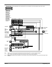
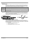
[71]
[496] Jog/Slack
AUX I/O
Diagnostic
connection
[105]
[72]
[228] Mode
Jog/Slack
Diagnostic
connection
[108]
[73]
[119] I DMD Isolate
Current Loop
Diagnostic
connection
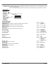
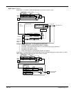
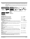
[494] Destination Tag 497
Tag Parameter
Setting
Digital
Input 4
C4
Digital Input 4 – DIGIN E (C4)
[494]
[497] Enable
AUX I/O
[495] Destination Tag 392
Tag Parameter
Setting
Digital
Input 5
C5
Digital Input 5 – DIGIN R (C5)
[495]
[620] Ramp Invert
Ramps
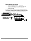
AM
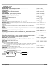
Optional DC contactor
“AM” auxiliary interlock
with drive enable.
Enable
C9
+24V
[69]
Diagnostic
connection
[70]
Diagnostic
connection
Parameter Descriptions
Destination Tag (Output)
The destination Tag No. assigned to the digital input.
Range: 0 to 549
Value for True
The value that output assumes when input is true.
Range: –300.00 to 300.00 %
Value for False
The value that output assumes when input is false.
Range: –300.00 to 300.00 %
Digital Inputs 1, 2 , and 3 (Also see AUX I/O and Diagnostics blocks)
Refer to the diagnostics function block description.
Range: 0 : Off
1 : On
Digital Input C4 (Also see AUX I/O and Diagnostics Parameters).
Electronic enable/quench terminal (On=Enable). If terminal C4 is used for anything other than
“Drive Enable” ([494] is not set to 497), then the enable parameter [497] must be set to ON or the
drive will not run.
Digital Inputs C4 and C5 have destination tags only.
Note: Value true is fixed at 0.01%, and value false is fixed at 0.00%.
Range: 0 to 549
Digital Input C5 (Also see AUX I/O and Diagnostics Parameters).
Reverse is active when C5 is true. This causes [620] Ramp Invert to revese (change polarity) of the
ramped output signal to Setpoint 1 [289] of the Speed Loop.
Digital Inputs C4 and C5 have destination tags only.
Note: Value true is fixed at 0.01%, and value false is fixed at 0.00%.
Range: 0 to 549