


6-4 Programming MN792
Parameter Descriptions
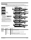
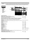
Analog Inputs Five analog input blocks are used to scale and clamp the inputs for terminals A2 through A6.
Analog input 1 is the 0–20mA or 4–20mA input. Analog input 2 is the main speed loop input (without
Accel/Decel ramps). Analog input 3 is Speed setpoint no. 3. Analog input 4 is the negative current clamp; this is
only active if bipolar clamps are enabled; ANIN 5 – Main current limit (or positive current clamp if bipolar clamps
are enabled. ANIN 4 is then the Negative current clamp input).
1 SYSTEM
2 CONFIGURE I/O
3 ANALOG INPUTS
4 ANIN 1 (A2)
4 ANIN 2 (A3)
4 ANIN 3 (A4)
4 ANIN 4 (A5)
4 ANIN 5 (A6)
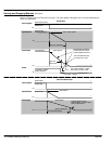
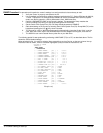
Calibration
MAX Value
MIN Value
Destination Tag *
[231] Max Value +100.00%
[230] Calibration 1.0000
Tag Parameter Factory Setting
[232] Min Value
-100.00%
[246] Destination Tag 100
Analog
Input 1
Analog Input 1 – ANIN 1 (A2)
[100] Input 1
Setpoint Sum 1
Factory Setting
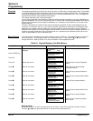
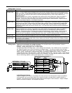
* ANIN 2 (A3) Notes:
1. ANIN 2 output [493] has two permanent connections:
a. SETUP PARAMETERS:: SPEED LOOP::
SETPOINTS:: RATIO 2 (A3) input and
b. SETUP PARAMETER:: CURRENT LOOP:: I DMD.
ISOLATE switch.
If you do not want ANIN 2 output [493] to be in the
Speed or Current Loops, set RATIO 2 (A3) [7] to zero,
and set I DMD. ISOLATE [119] to DISABLED.
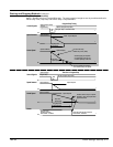
2. ANIN 2 (A3) is a direct input into the speed loop/current
loop and is scanned synchronously with the current
loop (typically every 3.33ms rather than every 7ms).
Therefore ANIN 2 should be used for any signal whose
response is critical.
3. Other tags can be connected to ANIN 2 output [493] for
access to the calibrated final value of ANIN 2.
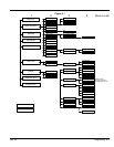
Diagnostic
connection
Diagnostic connection (tag accessible from the Diagnostic
Menu) allows monitoring of the raw analog input signals
from. within the Diagnostics parameter block.
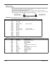
[234] Max Value
+100.00%
[233] Calibration 1.0000
Tag Parameter Factory Setting
[235] Min Value
-100.00%
Analog
Input 2
Analog Input 2 – ANIN 2 (A3)
[290] Setpoint 2 (A3)
Speed Loop
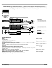
[237] Max Value
+100.00%
[236] Calibration 1.0000
Tag Parameter
Factory Setting
[238] Min Value
-100.00%
[249] Destination Tag 5
Analog Input 3 – ANIN 3 (A4)
[309] Input 0
Setpoint Sum 1
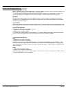
[240] Max Value +100.00%
[239] Calibration 1.0000
Tag Parameter
Factory Setting
[241] Min Value -100.00%
[250] Destination Tag 48
Analog Input 4 – ANIN 4 (A5)
[48] Neg I Clamp
Current Loop
[243] Max Value +100.00%
[242] Calibration 1.0000
Tag Parameter
Factory Setting
[244] Min Value -100.00%
[247] Destination Tag 301
Analog
Input 5
Analog Input 5 – ANIN 5 (A6)
[301] POS I Clamp
Current Loop
Current Loop
[119] I DMD Isolate
Fixed Outputs *
[50]
[246]
A2
A3
Diagnostic
connection
[51]
[249]
Diagnostic
connection
[52]
Analog
Input 3
A4
[493]
Analog
Input 4
A5
Diagnostic
connection
[53]
[250]
Diagnostic
connection
[54]
[247]
A6
500
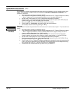
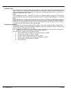
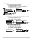
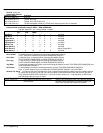
Keypad Menu: System::Configure I/O::Analog Inputs::Block Title
Block Title Parameter
Description
ANIN1 (A2)
ANIN2 (A3)
Calibration CALIBRATION
The analog input scaling ratio (gain factor).
ANIN3 (A4)
ANIN4 (A5)
MAX Value
MAX VALUE
The maximum value of the scaled analog input (max voltage clamp).
ANIN5 (A6)
MIN Value
MIN VALUE
The minimum value of the scaled analog input (min voltage clamp).
Destination Tag DESTINATION TAG [Output], (except ANIN 2)
The destination Tag No. to which the scaled analog input value is connected.
The destination of Output [493] ANIN2 is fixed. It is a calibrated scaled value.